Interconnection matrix for uncompetitive electrification, configuration and reconfiguration of FPGA (Field Programmable Gate Array)

A technology of electrical configuration and reconfiguration, applied in the field of interconnect matrix, to reduce current consumption, improve stability, and avoid device burnout

Active Publication Date: 2013-07-17
BEIJING MXTRONICS CORP +1
View PDF5 Cites 0 Cited by
  • Summary
  • Abstract
  • Description
  • Claims
  • Application Information

AI Technical Summary

Problems solved by technology

In this case, even if the second configuration itself does not cause competition, competition is likely to occur when changing from the first configuration to the second configuration

Method used


Image

  • Interconnection matrix for uncompetitive electrification, configuration and reconfiguration of FPGA (Field Programmable Gate Array)
  • Interconnection matrix for uncompetitive electrification, configuration and reconfiguration of FPGA (Field Programmable Gate Array)
  • Interconnection matrix for uncompetitive electrification, configuration and reconfiguration of FPGA (Field Programmable Gate Array)

Examples


Embodiment Construction

[0027] The present invention will be further introduced below in conjunction with the accompanying drawings.

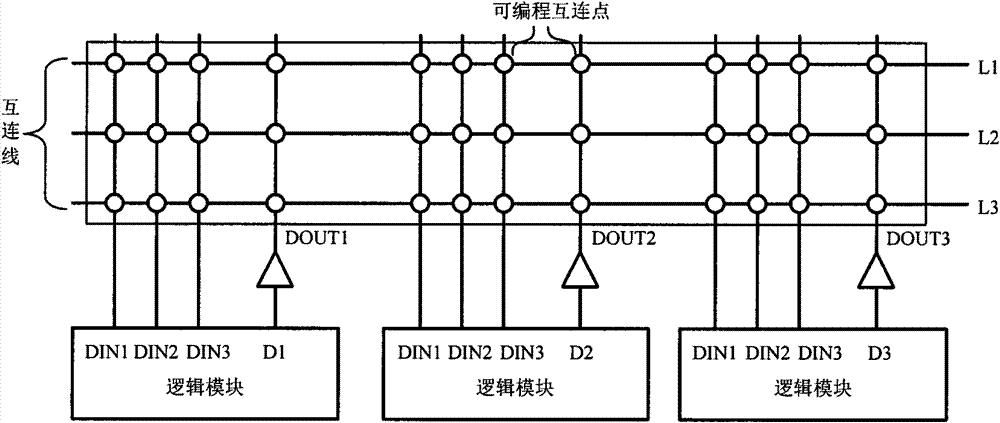
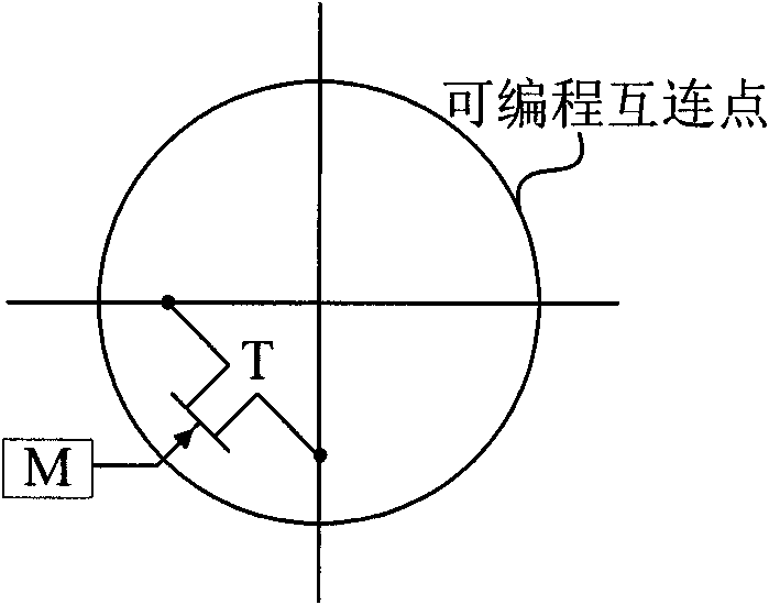
[0028] The interconnection matrix provided by the invention can eliminate the competition among the output drivers of the SRAM type FPGA in the process of power-on, configuration and reconfiguration. The interconnection matrix composed of interconnection lines and programmable interconnection points (PIPS) is an important part of FPGA. The interconnection lines are connected through programmable transmission pipes inside the programmable interconnection point (PIPS), and the programmable transmission pipes can control the connection and disconnection of these interconnection lines. Output signals from two sources, internal logic and I / O pins, are driven through the outputs, and passed through Programmable Interconnect Points (PIPS) and wires in all directions.

[0029] The non-competitive power-up, configuration and reconfiguration interconnection matrix of the prese...


PUM


Abstract

The invention discloses an interconnection matrix for uncompetitive electrification, configuration and reconfiguration of an FPGA (Field Programmable Gate Array), comprising a PIPS (Patterned Information Processing System) input point, a PIPS output point, a PIPS two-way point, a logic input controller and a three-state input controller. The input port of the PIPS input point is connected with the output end of a logic module through the logic input controller or directly connected with a power supply or the ground through the three-state input controller, wherein the logic module is connected to the interconnection matrix. The output port of the PIPS output point is connected with the input end of the logic module connected to the interconnection matrix. The outputs of the logic input controller and the three-state input controller are opened or closed under the control of an enable signal. By adopting the interconnection matrix, the problem of heavy current caused by inside signal competition in the processes of electrification, configuration and reconfiguration of an SRAM (System Random Access Memory) type FPGA is solved, and the load of a power supply system during electrification is reduced.

Description

technical field [0001] The invention belongs to the field of FPGA design, and relates to an interconnection matrix for FPGA non-competitive power-on configuration and reconfiguration. Background technique [0002] figure 1 It is a simple circuit diagram of a conventional FPGA interconnection matrix. FPGA is a combination of various logic modules. These logic modules are connected through the interconnection matrix. ) to connect the wires selectively. There are only 3 connections L1-L3 in the figure, but in the actual chip, there are many such connections, thus forming an interconnection matrix in the FPGA. This matrix includes programmable interconnection points (PIPS) and connections. The connection lines are connected with the input and output of each logic block, and the connection lines can be connected through programmable interconnection points (PIPS). figure 2 It is a conventional programmable interconnection point (PIPS) structure, and the source end and drain en...

Claims


Application Information

Patent Timeline
Patent Type & Authority Patents(China)
IPC IPC(8): H03K19/177
Inventor 刘增荣陈雷王愍李学武张彦龙周涛张帆孙华波尚祖宾
Owner BEIJING MXTRONICS CORP
Why Eureka
Try Eureka