Marble type railway lamp

A marble-type, track-based technology, applied in the field of track lights, can solve problems such as laborious movement, easy jamming, time-consuming and labor-intensive problems, and achieve the effect of solving tolerances, large currents, and strong durability

Pending Publication Date: 2018-11-27
箔晶智能照明(广东)有限责任公司
View PDF0 Cites 0 Cited by
  • Summary
  • Abstract
  • Description
  • Claims
  • Application Information

AI Technical Summary

Problems solved by technology

However, the slide between the power supply box and the track is in hard contact, which is laborious to move and easy to jam after long-term use. In ad

Method used


Image

  • Marble type railway lamp
  • Marble type railway lamp
  • Marble type railway lamp

Examples


Embodiment Construction

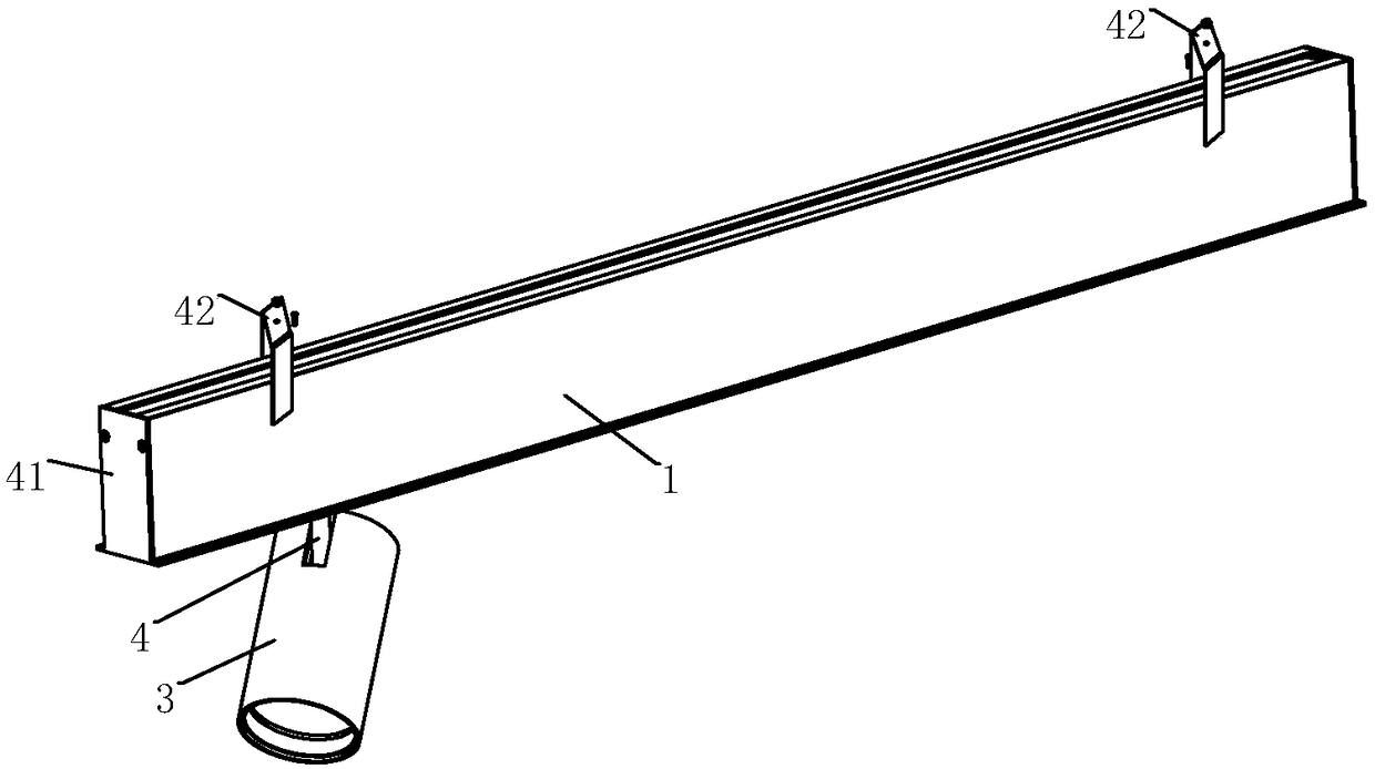
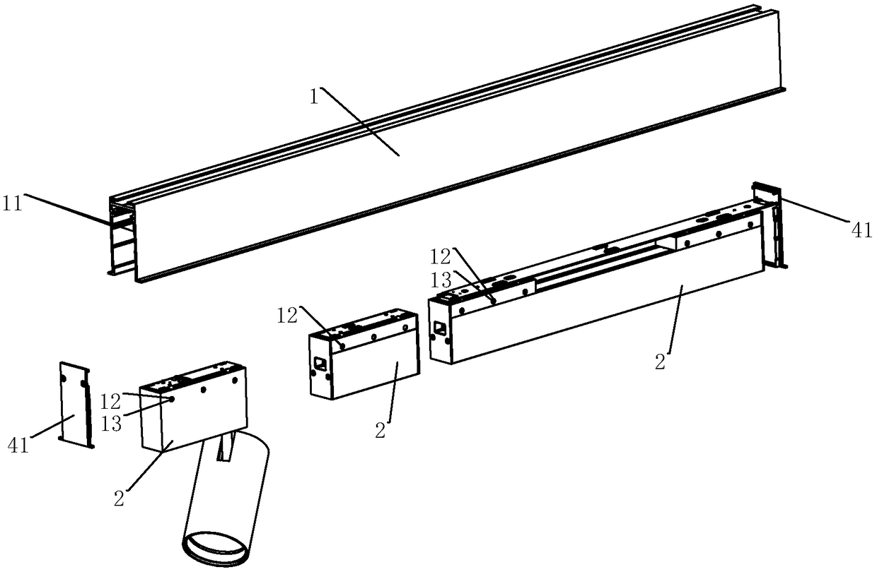
[0022] Such as Figure 1-Figure 2 As shown, it is a pinball-type track lamp of the present invention, which includes a track groove 1 and at least one lamp body 2 slidably arranged in the track groove 1. Third plugs 41 are arranged on both sides of the track groove 1, and the track The top of the tank 1 is connected with a fixed bracket 42 by bolts.

[0023] The two opposite inner walls of the track groove 1 are provided with opposite ball grooves 11, and the ball grooves 11 are in the same sliding direction as the lamp body 2;

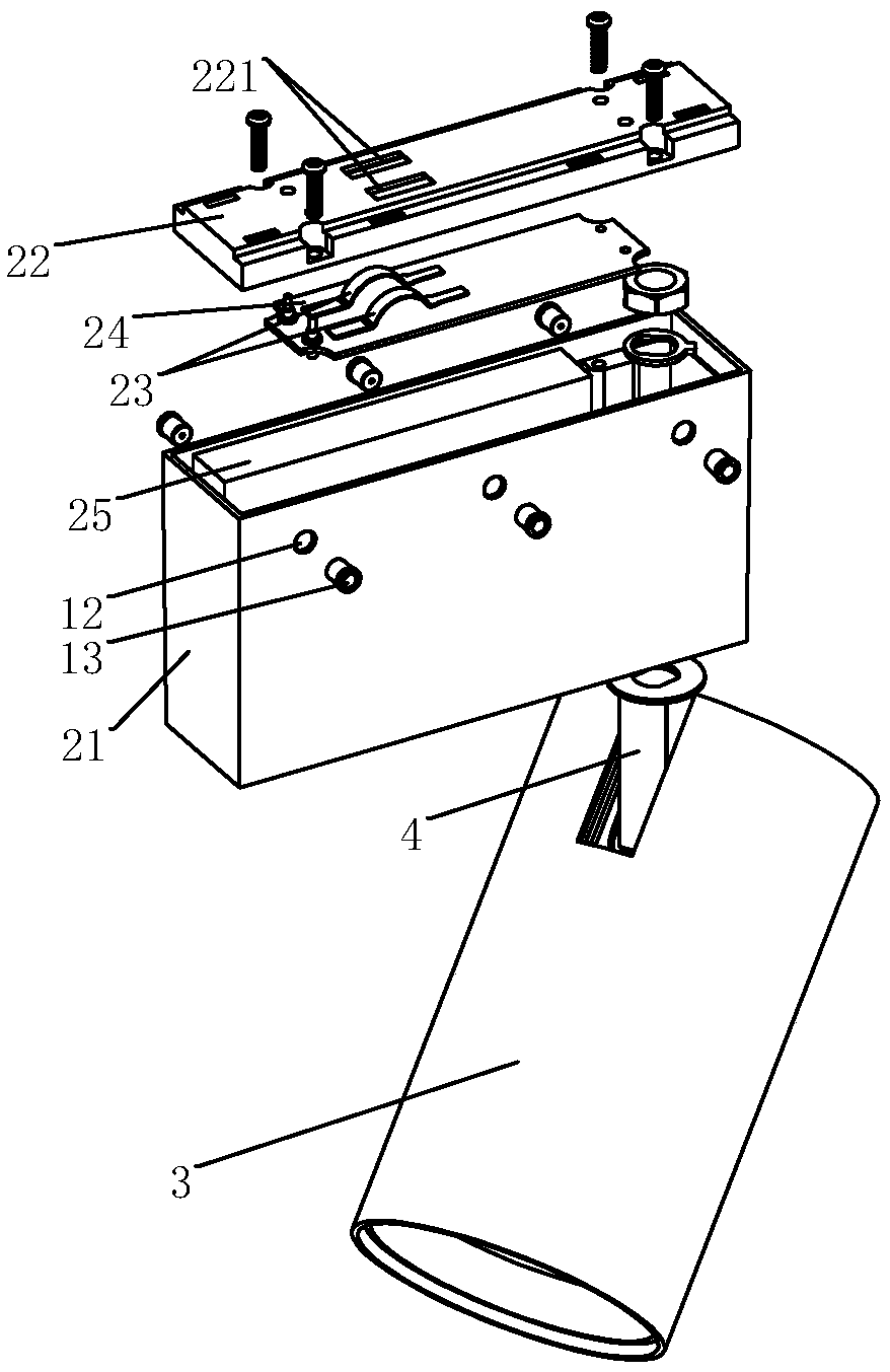
[0024] The two side walls of the lamp body 2 in contact with the track groove 1 are respectively provided with a plurality of mounting holes 12, and the mounting holes 12 are connected with balls 13 through elastic members, and the balls 13 leak outside the mounting holes 12 and are connected with the balls. Groove 11 is a rolling fit. The elastic member may be a spring, a shrapnel or other known elastic members.

[0025] Its working mechanism is t...


PUM


Abstract

The invention discloses a marble type railway lamp. The lamp comprises a railway groove and at least one lamp body slidably arranged in the railway groove; rolling ball grooves of opposite positions are formed in the two opposite inner walls of the railway groove, and the directions of the rolling ball groove are consistent with the sliding directions of the lamp bodies; several installing holes are formed in the two side walls, in contact with the railway groove, of the lamp bodies, rolling balls are connected with the installing grooves through elastic pieces, and the rolling balls are exposed outside the installing holes and in rolling cooperation with the rolling ball grooves. According to the railway lamp, the elastic rolling balls are installed on the lamp bodies and in rolling cooperation with the rolling ball grooves in the railway groove, the lamp bodies can freely slide in the railway groove, compared with an ordinary hard contact railway strip, the lamp saves both time and labor, the durability is higher, the tension of the rolling balls can be utilized for ensuring that the lamp can be fixed in the railway groove, when dismantled, the lamp body can be directly pulled downward, and the rolling balls contract under the pulling effect, so that the lamp body can be taken out of the railway groove for maintaining or replacing.

Description

technical field [0001] The invention relates to a track light, in particular to a marble track light. Background technique [0002] The track light is a light installed on a similar track, and the irradiation angle can be adjusted arbitrarily. It is generally used as a spotlight in places that require key lighting. Traditional track lights are generally composed of a track, a power box, and a lamp body. The power box and the track are slidably connected to facilitate position adjustment, and the lamp body and the power box are pivotally connected to adjust the lighting angle. However, the slide between the power supply box and the track is in hard contact, which is laborious to move and easy to jam after long-term use. In addition, the plug at one end of the track must be removed for maintenance and replacement of the power supply box, which is time-consuming and labor-intensive. Contents of the invention [0003] In order to solve the above technical problems, the object...

Claims


Application Information

Patent Timeline
IPC IPC(8): F21S8/00F21V15/01F21V21/35F21V23/00F21V23/06
CPCF21S8/00F21V15/01F21V21/35F21V23/003F21V23/06
Inventor 冯祖强
Owner 箔晶智能照明(广东)有限责任公司
Why Eureka
Try Eureka