Optical fiber testing method, device and passive optical network system

一种光纤测试、光纤网络的技术,应用在传输监视/测试/故障测量系统、传输系统、选择装置等方向,能够解决检测范围小、无法进一步增大TIA接收动态范围等问题,达到增大有效检测范围的效果

Active Publication Date: 2016-05-25
HUAWEI TECH CO LTD
View PDF5 Cites 0 Cited by
  • Summary
  • Abstract
  • Description
  • Claims
  • Application Information

AI Technical Summary

Problems solved by technology

[0003] Since the OTDR needs to be able to detect very weak and very strong test signals, the transimpedance amplifier (Transimpedance Amplifier, TIA) in the OTDR system is required to have high sensitivity and large receiving dynamic range. When the signal is strong, the reception is saturated. On the other hand, due to the limitation of the existing power supply capacity, the receiving dynamic range of the TIA cannot be further increased. Therefore, the detection range of the OTDR test signal in the prior art is relatively small

Method used


Image

  • Optical fiber testing method, device and passive optical network system
  • Optical fiber testing method, device and passive optical network system
  • Optical fiber testing method, device and passive optical network system

Examples


Embodiment Construction

[0016] The following will clearly and completely describe the technical solutions in the embodiments of the present invention with reference to the accompanying drawings in the embodiments of the present invention. Obviously, the described embodiments are only some, not all, embodiments of the present invention. Based on the embodiments of the present invention, all other embodiments obtained by persons of ordinary skill in the art without creative efforts fall within the protection scope of the present invention.

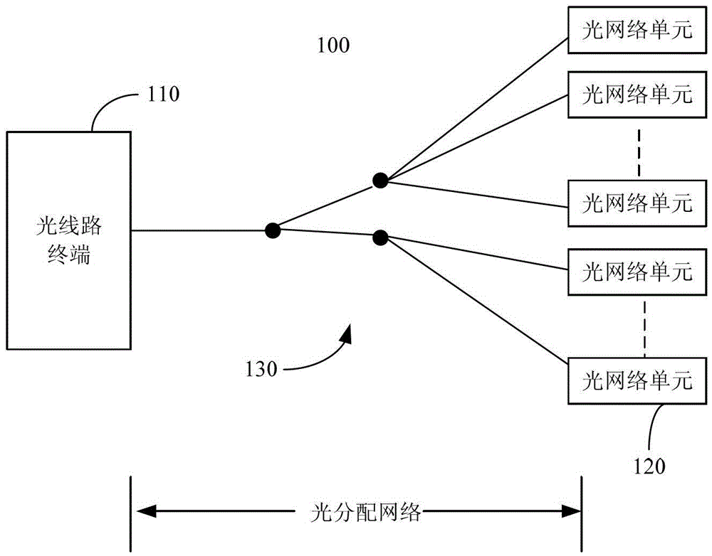
[0017] In order to better understand the present invention, the structure of a passive optical network (PON) system to which the optical fiber testing method provided in this application can be applied is firstly introduced below. see figure 1 , the passive optical network system 100 may include at least one optical line terminal 110 , a plurality of optical network units 120 and an optical distribution network 130 . The optical line terminal 110 is connected to t...


PUM


Abstract

The embodiment of the invention discloses an optical fiber testing method and a device thereof, which relate to the technical field of optical communication. The optical fiber testing method includes: receiving a test optical signal from an optical fiber network, and converting the test optical signal into a test current signal; the transimpedance amplifier adopts a first working mode to receive the test current signal and output a first test voltage signal ; Obtain the swing of the first test voltage signal, and determine whether the swing of the first test voltage signal satisfies a preset condition; when the swing of the first test voltage signal satisfies the preset condition, The transimpedance amplifier adopts the second working mode to receive the test current signal and output the second test voltage signal, wherein the upper limit and lower limit of the receiving dynamic range when the transimpedance amplifier works in the first working mode and the upper limit and lower limit of the receiving dynamic range when the transimpedance amplifier works in the first working mode; The two working modes are different. The embodiment of the present invention also provides a passive optical network system.

Description

technical field [0001] The present invention relates to the field of optical fiber testing, in particular to an optical fiber testing method, device and passive optical network (Passive Optical Network, PON) system. Background technique [0002] At present, with the acceleration of optical input and copper output, the construction of passive optical networks is developing rapidly, and PON needs to be installed, accepted and maintained. Positioning and exclusion play an important role. [0003] Since the OTDR needs to be able to detect very weak and very strong test signals, the transimpedance amplifier (Transimpedance Amplifier, TIA) in the OTDR system is required to have high sensitivity and large receiving dynamic range. When the signal is strong, the reception is saturated. On the other hand, due to the limitation of the existing power supply capacity, the receiving dynamic range of the TIA cannot be further increased. Therefore, the detection range of the OTDR test sign...

Claims


Application Information

Patent Timeline
Patent Type & Authority Patents(China)
IPC IPC(8): H04B10/08H04B10/12H04Q11/00H04B10/071
CPCH04B10/071H04B10/07
Inventor 钟德刚李泽彬余长亮李胜平
Owner HUAWEI TECH CO LTD
Why Eureka
Try Eureka