air conditioner indoor unit

A technology for indoor units and air conditioners, which is applied in air conditioning systems, mechanical equipment, space heating and ventilation, etc. It can solve the problems of undetectable human body movement and inability to properly control the operation status of the indoor unit A of the air conditioner, so as to achieve effective expansion Detection range and the effect of reducing the possibility of detection blind spots

Active Publication Date: 2018-08-21
DAIKIN IND LTD
View PDF11 Cites 0 Cited by
  • Summary
  • Abstract
  • Description
  • Claims
  • Application Information

AI Technical Summary

Problems solved by technology

[0005] However, the detection range of the infrared sensor is concentrically radiating with the sensor as the center, and its three-dimensional shape is a roughly conical shape with a certain volume. Therefore, it is installed in such a way that the air outlet panel with the air outlet is perpendicular to the ceiling of the room In the case of the air conditioner indoor unit, for example, such as Figure 13 As shown, the indoor unit of the air conditioner (refer to the symbol A in the figure) is usually installed on one side of the room R. Therefore, if the infrared sensor H is simply installed so that the central axis C1 of its cone-shaped detection range is relative to the air conditioner The front and rear direction of indoor unit A ( Figure 13 The left and right directions in the room) are vertical, and it is easy to produce a detection blind spot of the infrared sensor H in the room R (refer to Figure 13 area S in the room), this will cause the following problem: Even if the person is in the area S in the room R, the infrared sensor H cannot detect the movement of the human body, and the indoor unit A of the air conditioner cannot monitor the indoor unit A of the air conditioner according to the movement of the human body. proper control of the operating conditions of the

Method used


Image

  • air conditioner indoor unit
  • air conditioner indoor unit
  • air conditioner indoor unit

Examples


Embodiment Construction

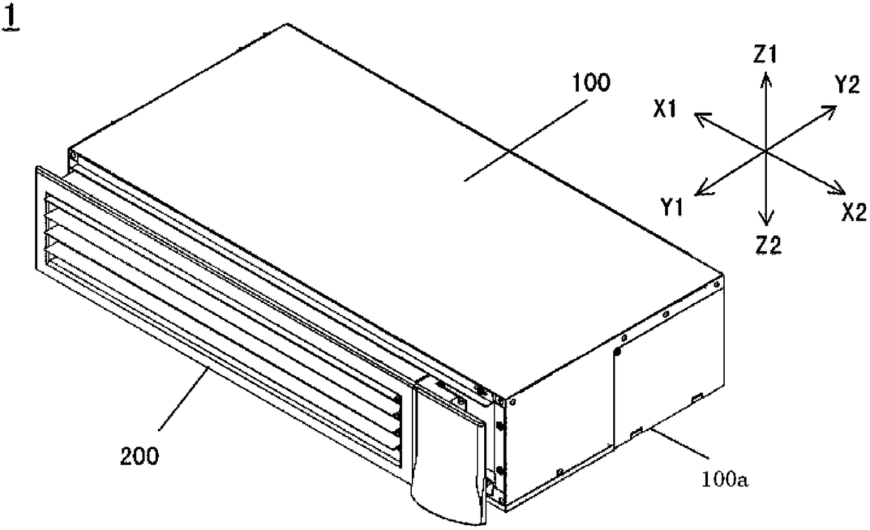
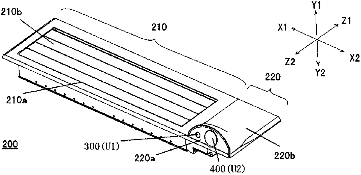
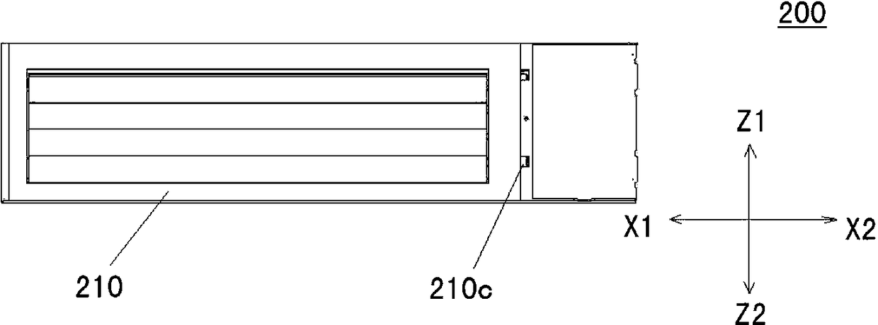
[0037] In the following description, let X be the longitudinal direction of the indoor unit of the air conditioner, Y be the width direction of the indoor unit of the air conditioner, and Z be the height direction of the indoor unit of the air conditioner. The longitudinal direction X may also be referred to as a "left-right direction", the width direction Y may be referred to as a "front-rear direction", and the height direction may be referred to as a "vertical direction". Sometimes the side in the longitudinal direction X is called "X1 direction" or "left side", the other side in the longitudinal direction X is called "X2 direction" or "right side", and the side in the width direction Y is called "Y1 direction" or "front", the other side of the width direction Y is called "Y2 direction" or "rear", the side of the height direction Z is called "Z1 direction" or "upper", and the height direction Z The other side is called "Z2 direction" or "below".

[0038] Next, an embodimen...


PUM


Abstract

Provided is an air conditioner indoor unit. The effective detecting range of a sensor which is used for detecting a heat source zone in an air conditioner object space can be expanded. The air conditioner indoor unit comprises an indoor unit body and an air outlet face plate arranged on the indoor unit body. According to arrangement of the air conditioner indoor unit, the air outlet face plate can be perpendicular to the bottom face of the indoor unit body, the air outlet face plate is provided with an air outlet, and the sensor for detecting the air conditioner object space is arranged. According to arrangement of the sensor, the center axis of the detecting range of the sensor is oblique in the up-down direction relative to the plane where the air outlet is formed, so that the detecting range is toward the air conditioner target space.

Description

technical field [0001] The present invention relates to an air conditioner indoor unit, and more particularly to an air conditioner indoor unit having a sensor for detecting a heat source in a space to be air-conditioned. Background technique [0002] In the conventional air conditioner indoor unit, the user can manually adjust the temperature and direction of the air blown from the air outlet of the air conditioner indoor unit by using a remote controller so as to blow air at an appropriate temperature into the room (air-conditioning target space). [0003] However, in this air conditioner indoor unit, since the user needs to manually adjust it, in order to obtain a comfortable wind when the user frequently flows in the room, it is necessary to frequently adjust it by hand, which is inconvenient to operate. question. [0004] In order to solve the above problems, for example, as described in Patent Document 1, it can be considered to use an infrared sensor to detect the mo...

Claims


Application Information

Patent Timeline
Patent Type & Authority Patents(China)
IPC IPC(8): F24F1/00F24F11/89F24F120/10
Inventor 郁巍东孙洁
Owner DAIKIN IND LTD
Why Eureka
Try Eureka