A Method for Extracting Arrival Time of Guided Wave Signals with Low SNR Applicable to Guided Wave Transducer Array

A transducer array and low signal-to-noise ratio technology, which is applied in the processing of detection response signals, the use of sound waves/ultrasonic waves/infrasonic waves to analyze solids, instruments, etc., can solve the problem of limiting the detection range of guided waves and the inability of guided wave array signal processing methods Extract information and other issues to achieve the effect of improving the effective detection range

Active Publication Date: 2020-07-24
哈尔滨工业大学人工智能研究院有限公司
View PDF13 Cites 0 Cited by
  • Summary
  • Abstract
  • Description
  • Claims
  • Application Information

AI Technical Summary

Problems solved by technology

[0005] The purpose of the present invention is to solve the problem that the existing guided wave array signal processing method cannot extract information from the received signal with low signal-to-noise ratio, thus limiting the detection range of the guided wave. Extraction method of arrival time of guided wave signal with signal-to-noise ratio

Method used


Image

  • A Method for Extracting Arrival Time of Guided Wave Signals with Low SNR Applicable to Guided Wave Transducer Array
  • A Method for Extracting Arrival Time of Guided Wave Signals with Low SNR Applicable to Guided Wave Transducer Array
  • A Method for Extracting Arrival Time of Guided Wave Signals with Low SNR Applicable to Guided Wave Transducer Array

Examples


specific Embodiment approach 1

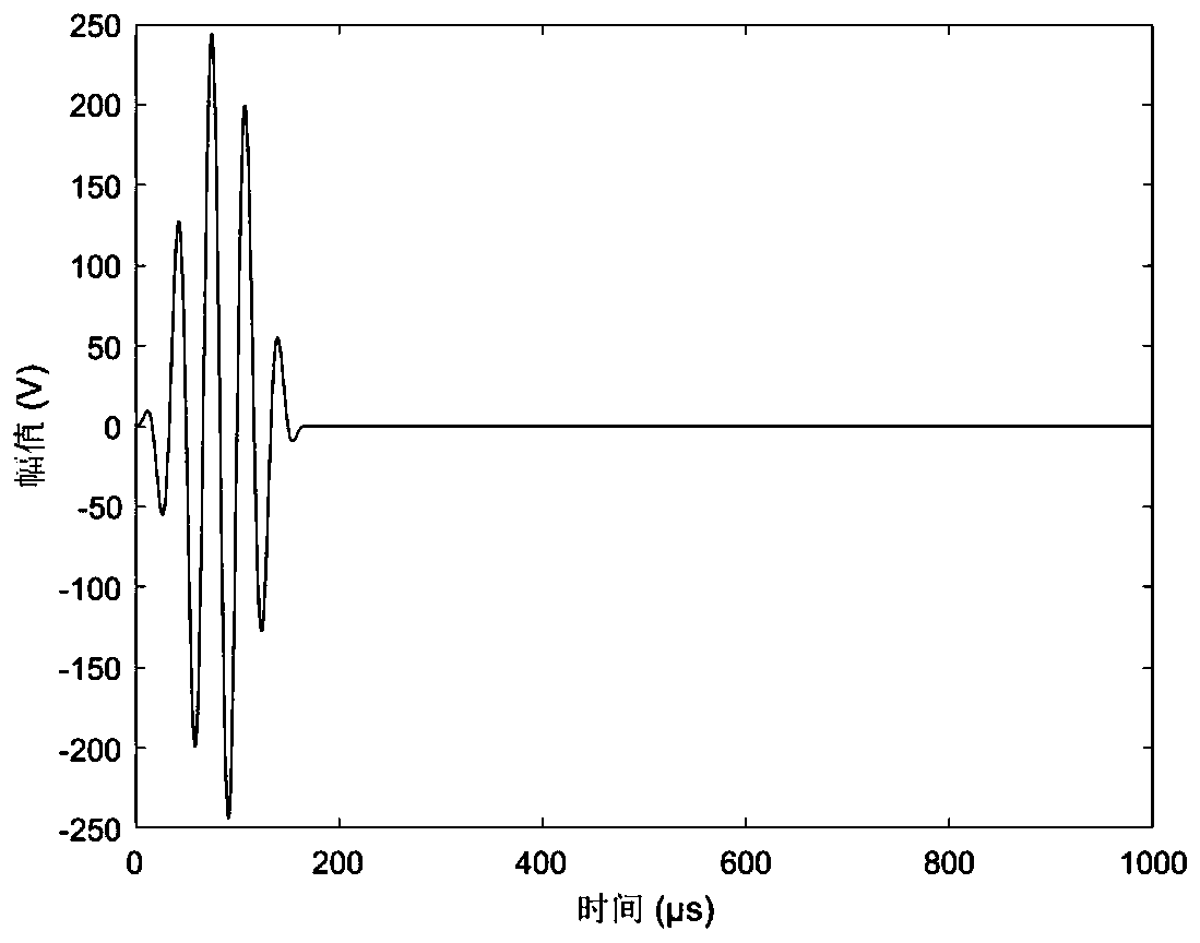
[0047]Specific Embodiment 1: A method for extracting the arrival time of a guided wave signal with a low signal-to-noise ratio applicable to a guided wave transducer array described in this embodiment uses the excitation signal to excite the wave signal in the waveguide, and uses the transducer array Each transducer in the waveguide collects damage scattering signals from the far field in the waveguide, and the damage scattering signals collected by all transducers form a guided wave detection signal matrix, and the excitation signal is a simple harmonic signal of n wave peak plus Hann window , its expression x(t) is:

[0048]

[0049] Among them, A w is the peak value of the excitation signal, H(t) is the step function, n is the number of peaks, f c is the center frequency of the excitation signal;

[0050] Then the expression of the envelope width of the excitation signal is:

[0051] Δt=n / f c .

[0052] The transducer array is an equidistant linear array that includ...

Embodiment 1

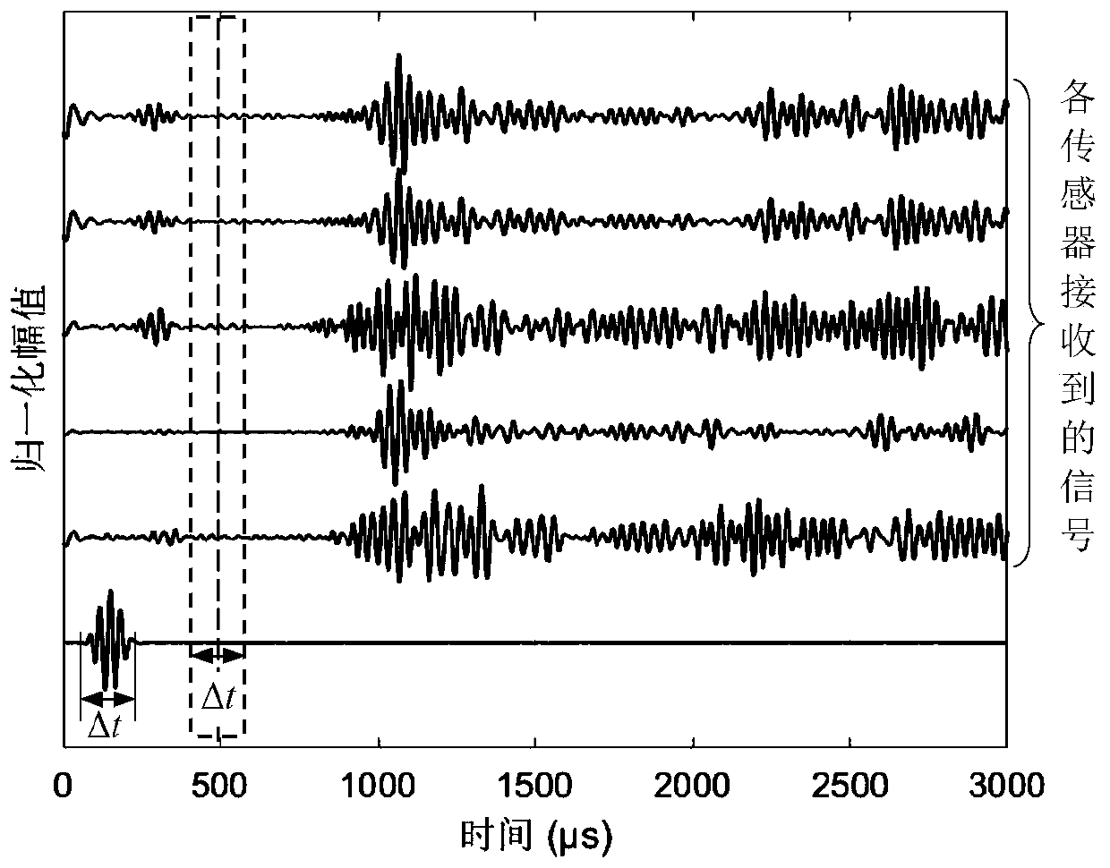
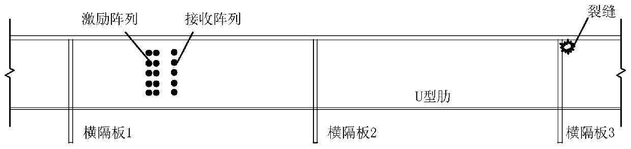
[0084] In this embodiment, the linear array is used to detect the fatigue cracks of the actual orthotropic steel bridge deck, and the ultrasonic guided wave signal received by the linear array is processed. The layout of the linear array in the actual orthotropic steel bridge deck and the location of the damage are as follows: figure 2 As shown, there is a fatigue crack at the junction of the diaphragm 3 and the U-shaped rib of the bridge deck. After the excitation array excites the 30kHz ultrasonic guided wave on the U-shaped rib of the actual orthotropic steel bridge deck, each sensor of the receiving array receives the guided wave signal, and the signal obtained after subtracting the reference signal at the undamaged position is the fatigue crack reflex generation, see Figure 4 , it can be seen that because the damage is far away from the excitation and receiving transducer arrays, and there are two diaphragms between them, the waveform of the received damage scattering ...

Embodiment 2

[0086] This method is used to process the signal of circular array detection actual steel pipe with welded seam. The layout of the circular array on the actual steel pipe and the position of the weld are as follows: Figure 7 shown. After the excitation array excites the 120kHz ultrasonic guided wave on a steel pipe with a diameter of 32cm, each sensor of the receiving array receives the guided wave signal, and the received signal is shown in Figure 9 . Since the sensor is far away from the weld seam, the waveform of the received guided wave signal is complex and the signal-to-noise ratio is low. Figure 10 The result of processing the guided wave array signal by this method is given, and the arrival time of the reflected signal of the weld can be clearly obtained, and the position of the first weld and the second weld can be further obtained from this. The detection results are consistent with match the actual location.


PUM


Abstract

The invention discloses a low signal-to-noise ratio guided wave signal arrival time extraction method suitable for a guided wave transducer array and relates to the field of ultrasonic nondestructivedetection. The invention aims to solve the problem that an existing guided wave array signal processing method cannot extract information from a received signal with a low signal-to-noise ratio, so that the guided wave detection range is limited. According to the invention, in a signal received by each array element in an ultrasonic guided wave transducer array, a damage scattering signal component has high correlation, the damage scattering signal component has no correlation with noise, so that a required damage scattering signal component can be extracted from an array receiving signal withlow signal-to-noise ratio, the effective detection range of guided waves is greatly improved, and the detection capability for a small damage is greatly improved.

Description

technical field [0001] The invention belongs to the field of ultrasonic nondestructive testing. Background technique [0002] Ultrasonic guided wave is a kind of ultrasonic wave that can propagate in structural members with limited boundaries such as thin plates, pipes, and rods. Compared with conventional ultrasonic waves, ultrasonic guided waves can propagate over a long distance and in a wide range in the above-mentioned structures. When encountering small structural defects or damages, in addition to the part that continues to propagate, waves will also be scattered or reflected at the defects. The analysis of the characteristics of the above-mentioned various source waves can identify the tiny defects or damages of the structure, and further analysis can locate, quantify and even image the defects. The structural damage identification method based on ultrasonic guided waves is sensitive to local micro-defects in the structure. Compared with traditional ultrasonic non-d...

Claims


Application Information

Patent Timeline
Patent Type & Authority Patents(China)
IPC IPC(8): G01N29/44G01N29/48G01N29/04
CPCG01N29/04G01N29/44G01N29/48G01N2291/0289G01N2291/044
Inventor 李惠周文松王鹏
Owner 哈尔滨工业大学人工智能研究院有限公司
Why Eureka
Try Eureka