
Raschel machine

A warp knitting machine and tie rod technology, which is applied in warp knitting, textiles, papermaking, knitting, etc., can solve the problems of reducing the speed, increasing the running noise, and increasing the size of the guide bar-transmission rod and tie rod, etc., so as to avoid The effect of contact

Inactive Publication Date: 2014-08-06
KARL MAYER TECH TEXTILIEN GMBH
View PDF9 Cites 0 Cited by
  • Summary
  • Abstract
  • Description
  • Claims
  • Application Information

AI Technical Summary

Problems solved by technology

[0006] At the same time, the increased swivel radius also means that the guide bar-transmission rods and tie rods are enlarged, so that larger masses have to be moved over longer strokes during the movement of the guide bar
This means that, in raschel machines, this construction reduces the maximum possible rotational speed and increases the running noise
This has obvious disadvantages compared to tricot machines of similar construction

Method used


Image

  • Raschel machine
  • Raschel machine
  • Raschel machine

Examples


Embodiment Construction

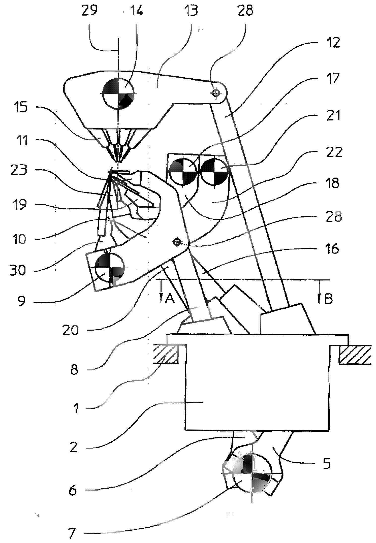
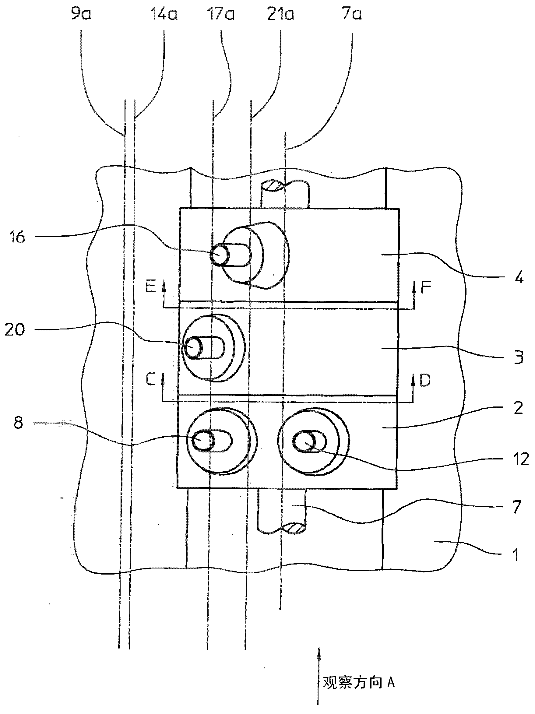
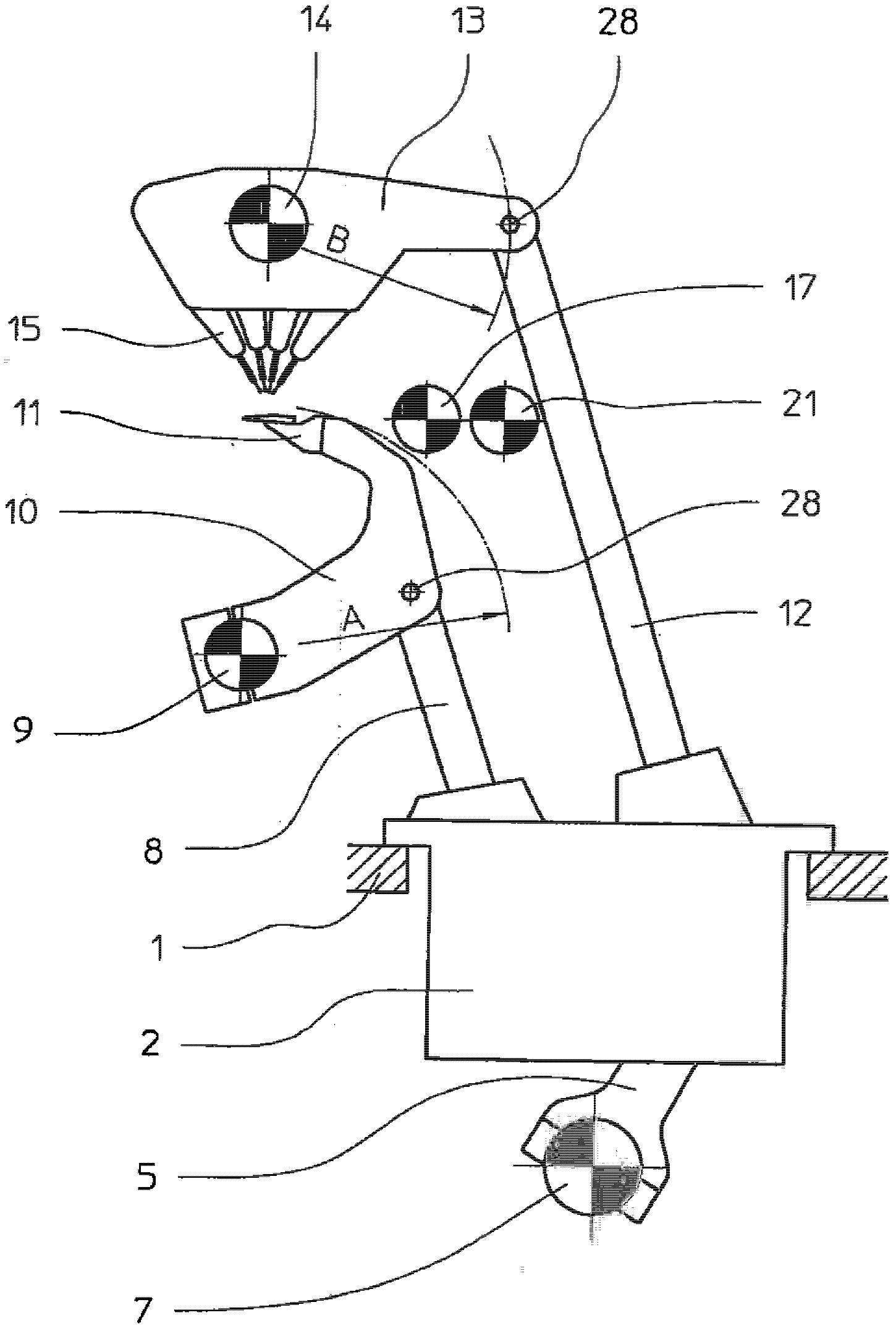
[0040] in the overview figure 1 and 2 shows that the drive of the raschel machine according to the invention has three drive units, which are essentially formed by three coupling groove drives (Koppelrastgetriebe) 2, 3 and 4. These drive units form the housing of the associated bayonet drive 2 , 3 and 4 . Via downwardly protruding connecting rods 5 and 6, the coupling drive gears 2, 3 and 4 are in drive connection with a crankshaft 7, which forms the drive shaft of the Raschel machine. The pull rods 8, 12, 16 and 20 protrude upwards from the coupling drive gear 2, 3 and 4, and these pull rods move the different comb bars 11, 15, 19 and twenty three. In addition, a drive joint 28 for force transmission is located between the coupling bay drives 2 , 3 and 4 and the tie rods 8 , 12 , 16 and 20 .

[0041] The drive unit can be a closed structural unit, which is fastened closely to one another on the machine tool 1 via the crankshaft 7, for which see figure 2 . However, the...


PUM


Abstract

The machine has bar drive levers (10,13) which are secured parallel to crankshaft (7) that is connected with coupling gear (2). The coupling gear drives the bar drive levers through tie rods (8,12) which lie in a common plane radial to the crankshaft. The tie rod (12) is connected to bar drive lever (13) and is displaced over the guide bars (15) while the tie rod (8) is phase shifted to that of the guide bars. The compound needles are provided on a needle bar (23) as knitting needles, driven by coupling gear and displaced in axial direction of crankshaft.

Description

technical field [0001] The invention relates to a raschel knitting machine with a drive shaft designed as a crankshaft extending in the longitudinal direction of the raschel knitting machine and such that the different knitting tools arranged on the bars are positioned relative to each other. In a coordinated movement, where each type of knitting tool is associated with an own transmission bar, wherein the bars are located on the bar transmission bar, which is fixed on the bar shaft extending parallel to the crankshaft ; the bar drive rod is made to perform a rotational movement through the pull rod by means of a coupling drive, which is itself driven by the crankshaft by means of a connecting rod; at least one first coupling drive is provided, It is operatively connected to the crankshaft via a connecting rod with an additional articulation point and enables different movements of the first tie rod and the second tie rod, wherein the two tie rods lie on a common plane which i...

Claims


Application Information

Patent Timeline
Patent Type & Authority Patents(China)
IPC IPC(8): D04B27/26
CPCD04B27/08
Inventor 彼得·罗特克劳斯·格茨
Owner KARL MAYER TECH TEXTILIEN GMBH
Learn More