Inner barrel structure of washing machine and washing machine with inner barrel

A washing machine and inner tub technology, applied in the field of washing machines, achieves the effects of simple structure and low installation cost

Active Publication Date: 2012-10-17
QINGDAO HAIER WASHING MASCH CO LTD
View PDF6 Cites 24 Cited by
  • Summary
  • Abstract
  • Description
  • Claims
  • Application Information

AI Technical Summary

Problems solved by technology

[0006] However, in the flange structure of the above-mentioned washing machine, there is a large water-permeable gap between the bottom of the inner tub and the flange. Although the water-permeable gap can allow the washing water to circulate between the inner tub and the outer tub, it is difficult to use flexible cleaning particles to clean the inner tub and the outer tub. For the washing machine with the barrel wall, it can also make the soft particles between the inner barrel and the outer barrel enter the inner barrel through the gap, thereby reducing the number of soft particles between the inner barrel and the outer barrel, and affecting the effect of cleaning the walls of the inner barrel and the outer barrel

Method used


Image

  • Inner barrel structure of washing machine and washing machine with inner barrel
  • Inner barrel structure of washing machine and washing machine with inner barrel
  • Inner barrel structure of washing machine and washing machine with inner barrel

Examples


Embodiment 1

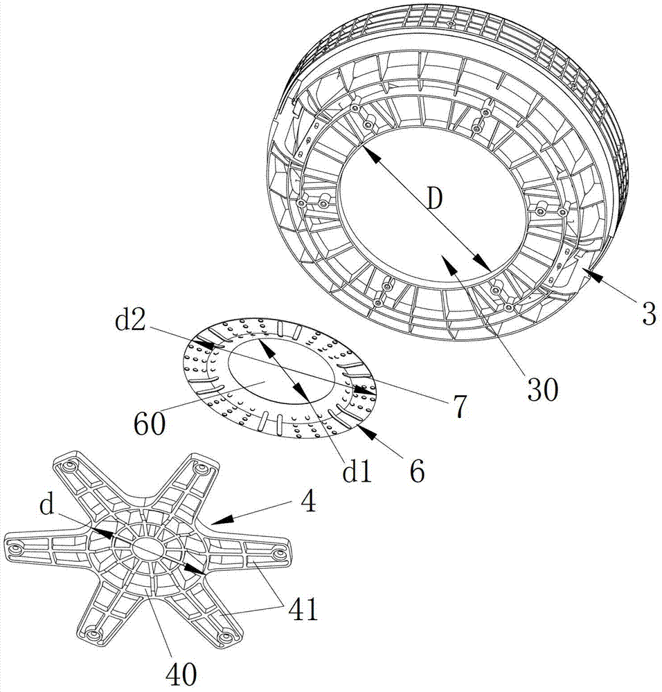
[0037] There are at least two types of the blocking cover, the flange plate and the bottom of the inner bucket described in the present invention which are integrally injection molded. The blocking cover 6 described in this embodiment is integrally injection-molded with the bottom 3 of the inner barrel, that is, d1≤d

Embodiment 2

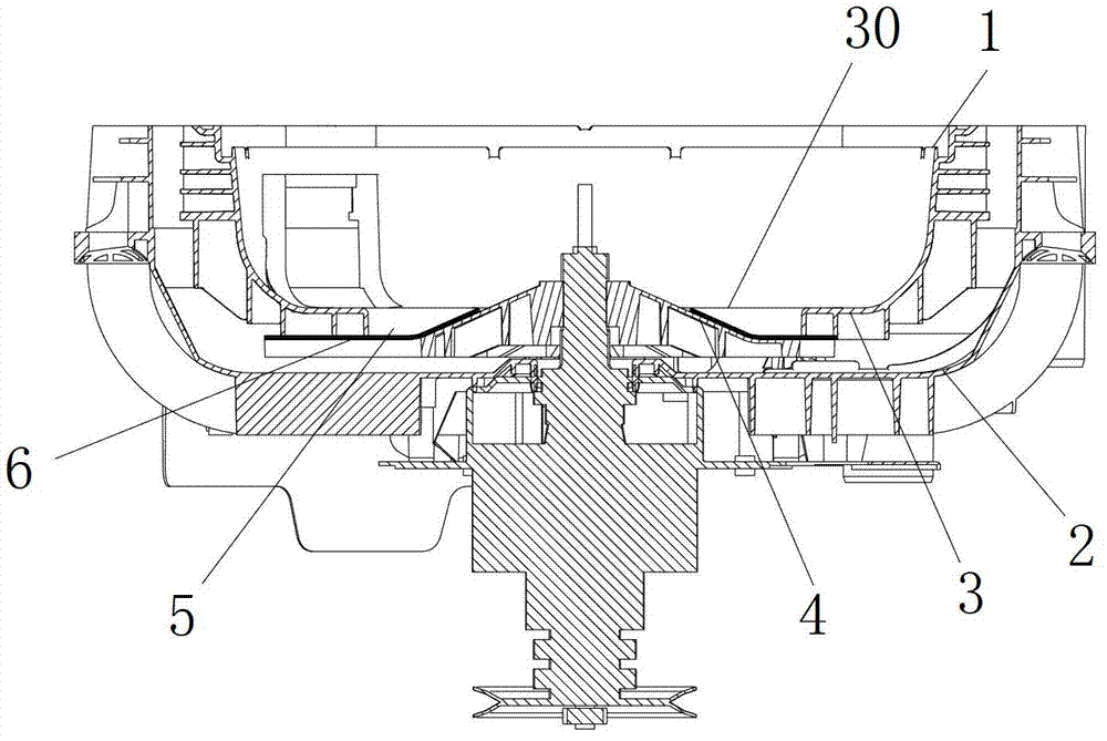
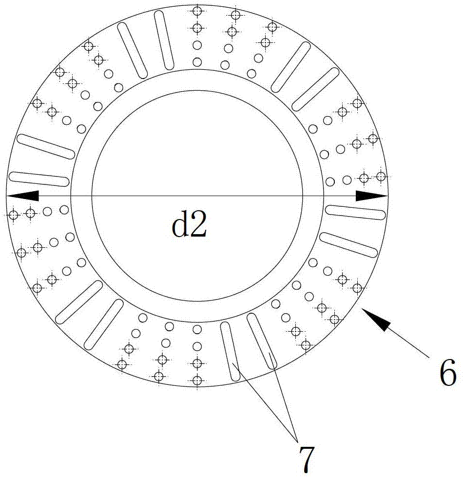
[0039] The difference between this embodiment and Embodiment 1 is that the blocking cover 6 is an independent cover body structure, the outer diameter d2 of the blocking cover is the same as the inner diameter D of the hollow area at the bottom of the inner barrel, and the blocking cover 6 is fitted and bonded to the bottom of the inner barrel and is hollow In area 30, such as image 3 As shown, the inner diameter d1 of the blocking cover 6 is smaller than the diameter d of the main body 40 of the flange, that is, the blocking cover 6 has a part of the annular cover overlapping with the main body 40 of the flange, and the permeable holes 7 are distributed outside the annular cover that does not overlap with the main body 40 The area corresponds to the space between two adjacent fixing feet 41 of the flange 4 . or, as in Figure 5 As shown, the buckle structure corresponding to the outside of the hollow area 30 at the bottom of the inner tub is buckled by the snapping structur...

Embodiment 3

[0041] The barrier cover 6 described in this embodiment is an independent cover body structure, the outer diameter d2 of the barrier cover is larger than the inner diameter D of the hollow area 30 at the bottom of the inner barrel, and is sandwiched between the flange plate 4 and the inner barrel by the flange plate fixing feet 41 Between bottom 3, satisfy d1≤d Figure 4 As shown, the inner diameter d1 of the blocking cover 6 in this embodiment may be equal to the diameter d of the flange main body 40 , and the water permeable hole 7 is arranged in the area between the two adjacent fixing feet 41 of the blocking cover 6 corresponding to the flange 4 .

[0042] Preferably, the blocking cover described in this embodiment is installed on the bottom of the inner tub, and then sandwiched between the flange and the bottom of the inner tub by means of a flange.


PUM


Abstract

The invention discloses an inner barrel structure of a washing machine and a washing machine with the inner barrel. The inner barrel is coaxially arranged in an outer barrel of the washing machine; cleaning particles for cleaning the walls of the barrels are arranged between the inner barrel and the outer barrel; a flange plate is arranged at the bottom part of the inner barrel; the flange plate and a hollow area at the bottom part of the inner barrel form a permeable channel; a baffle cover for preventing the cleaning particles from entering into the inner barrel via the permeable channel is arranged between the bottom part of the inner barrel and the flange plate; a permeable hole is formed on the baffle cover corresponding to the permeable channel; the baffle cover is a hollow annular cover body; and a protruding main body at the centre of the flange plate correspondingly blocks a hollow position of the baffle cover, and the permeable hole is distributed at the position of the annular cover body corresponding to the permeable channel. According to the invention, the structure of the baffle cover is simple; the installation cost is low; the cleaning particles between the inner barrel and the outer barrel can be prevented from entering into the inner barrel, and the problem that the cleaning particles enter into the inner barrel to affect the barrel wall cleaning effect is avoided.

Description

technical field [0001] The invention relates to the field of washing machines, in particular to an inner tub structure of a washing machine and a washing machine with the inner tub. Background technique [0002] There is a closed environment between the inner and outer barrels of the existing washing machine, and only water can pass through. Due to the limitations of the above-mentioned structure of the washing machine and the particularity of the use environment, after 3-5 months of use, the outer wall of the inner barrel and the outer barrel Dirt will adhere to the inner wall, thereby breeding different degrees of bacteria, and most of the bacteria that grow are harmful to the human body. [0003] Along with the raising of people's living standard and the raising of the quality of life requirement, the solution of the hygienic problem of washing machine has shown very urgent. According to the investigation of the internal environment of the washing machine by relevant sci...

Claims


Application Information

Patent Timeline
Patent Type & Authority Applications(China)
IPC IPC(8): D06F37/12D06F39/12
Inventor 舒海李海涛邓秀文赵新宇
Owner QINGDAO HAIER WASHING MASCH CO LTD
Why Eureka
Try Eureka