
Gypsum powder continuous calcining device

A calcining device and gypsum powder technology are applied in the field of gypsum powder production, which can solve the problems of large dust, affect the calcination of gypsum powder, reduce the filter effect of cloth bags, etc., and achieve the effects of ensuring dust reduction efficiency, production efficiency, and calcination efficiency.

Active Publication Date: 2022-07-26
康定龙源穗城石膏有限责任公司
View PDF5 Cites 1 Cited by
  • Summary
  • Abstract
  • Description
  • Claims
  • Application Information

AI Technical Summary

Problems solved by technology

Some gypsum calcination processes are first ground and then fired, and some are first fired and then ground. Corresponding to the gypsum powder that is first ground and then fired, most of them are calcined in a frying pan, but the gypsum powder calcined in a frying pan cannot achieve continuous production, and the dust is large, so some choose Rotary kiln is used for calcination process. Since gypsum powder contains moisture, gypsum powder will easily mix with water vapor during calcination. On the one hand, it will affect the calcination effect of gypsum powder. , most of them are collected with cloth bags, but the water vapor in the air will cause the gypsum powder to adhere to the cloth bag, thereby reducing the filtering effect of the cloth bag and affecting the calcination of gypsum powder. Therefore, a continuous calcination equipment suitable for gypsum powder is needed

Method used


Image

  • Gypsum powder continuous calcining device
  • Gypsum powder continuous calcining device
  • Gypsum powder continuous calcining device

Examples


Embodiment

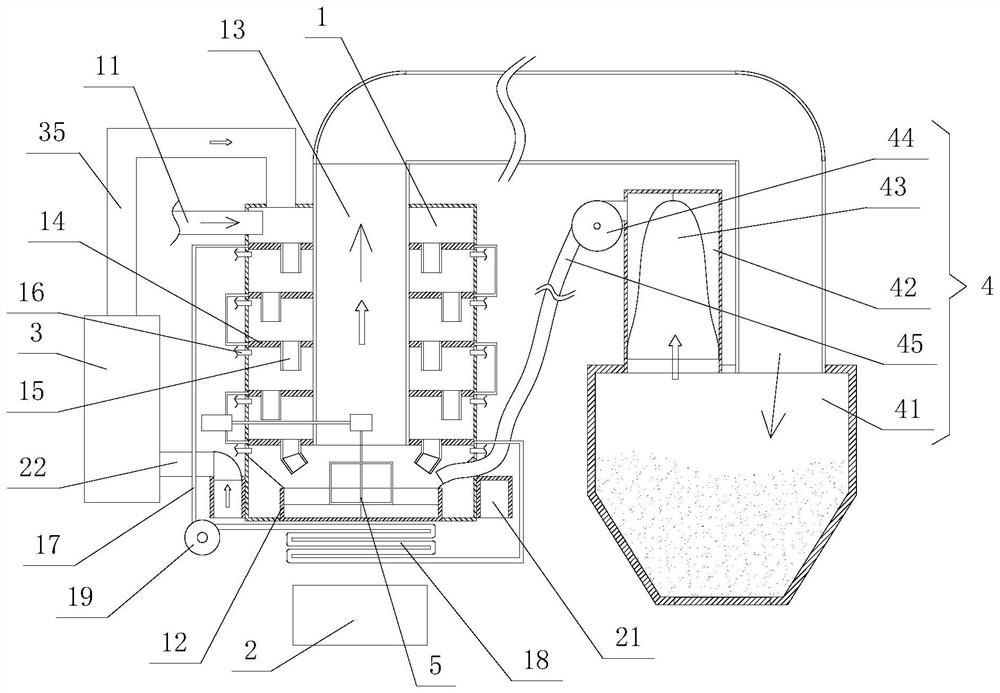
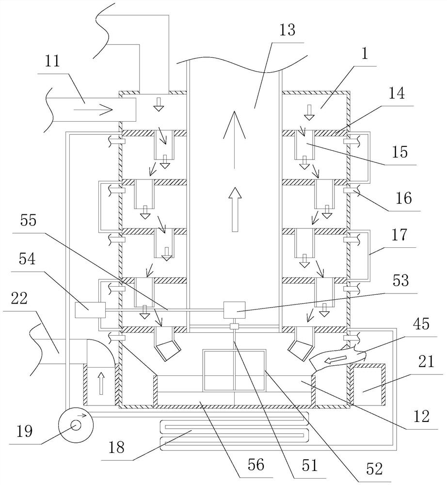
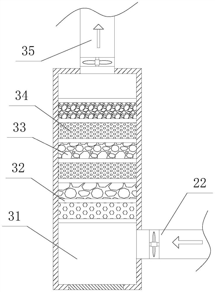
[0023] figure 1 It is a schematic structural diagram provided by an embodiment of the present invention, figure 2 A schematic diagram of the internal structure of the calcining cylinder provided in the embodiment of the present invention, image 3 It is a schematic diagram of the internal structure of the filter provided by the embodiment of the present invention, wherein the hollow arrow is the flow direction of the air, and the solid arrow is the flow direction of the gypsum powder. The continuous calcining device for the gypsum powder provided in this embodiment includes a calcining cylinder 1, a burner 2, and a filter 3. and the dust suppression device 4, the calcining cylinder 1 is vertically arranged, a receiving tray 12 is installed at the bottom of the calcining cylinder 1, and a guide cylinder 13 is set inside the calcining cylinder 1 above the receiving tray 12. The guide cylinder 13 and the calcining cylinder 1 A multi-layer preheating plate 14 is installed betwee...


PUM


Abstract

The invention discloses a gypsum powder continuous calcining device which comprises a calcining cylinder, a combustor, a filter and a dust falling device, a material receiving tray is installed at the bottom of the calcining cylinder, a guide cylinder is installed above the material receiving tray in a sleeving mode, multiple layers of preheating plates are installed between the guide cylinder and the calcining cylinder, and guide pipes extending downwards are installed on the preheating plates; an exhaust pipe is installed at the bottom of the preheating plate, a combustor is installed below the calcining cylinder, a gas collecting hood is arranged on the combustor and connected with a filter, an air supply pipe is connected to the filter and installed on the top between the calcining cylinder and the guide cylinder, and the top end of the guide cylinder penetrates through the calcining cylinder and then is connected with a dust falling device. By arranging the calcining cylinder, sleeving the guide cylinder in the calcining cylinder and cooperating with the preheating plate, the gypsum powder can be pre-dried, the dried water vapor is discharged from the exhaust pipe, and the moisture in the calcining cylinder can be reduced, so that the situation that the collection of the gypsum powder is influenced by more water vapor after the gypsum powder is calcined is prevented, and meanwhile, the continuous calcining of the gypsum powder can be realized.

Description

technical field [0001] The invention relates to the field of gypsum powder production, in particular to a continuous calcining device for gypsum powder. Background technique [0002] Gypsum powder is a common material and is widely used in various fields of life. The calcination process of gypsum is first grinding and then burning, and some is first burning and then grinding. Corresponding to the gypsum powder that is first ground and then burned, most of them are calcined in a frying pan. However, the calcined gypsum powder in a frying pan cannot achieve continuous production, and there is a lot of dust, so some of them are selected for calcination. Rotary kiln is used for calcination. Since gypsum powder contains water, during calcination, gypsum powder is easily mixed with water vapor. On the one hand, it affects the calcination effect of gypsum powder. , Most of them are collected by cloth bags, but the moisture in the air will cause the gypsum powder to adhere to the c...

Claims


Application Information

Patent Timeline
Patent Type & Authority Applications(China)
IPC IPC(8): C04B11/036
CPCC04B11/036
Inventor 高帆
Owner 康定龙源穗城石膏有限责任公司
Learn More