
Temperature reducing device for air cylinder and oil cylinder

A technology for high-temperature equipment and oil cylinders, applied in mechanical equipment, fluid pressure actuation devices, fluid pressure actuation system components, etc., can solve the problems of reducing the service life of the cylinder, increasing the production cost, reducing the production efficiency, and extending the service life. , Save production costs and provide the effect of production efficiency

Inactive Publication Date: 2012-10-17
TAICANG HAIJIA VEHICLE FITTINGS
View PDF8 Cites 2 Cited by
  • Summary
  • Abstract
  • Description
  • Claims
  • Application Information

AI Technical Summary

Problems solved by technology

[0002] In the actual production process of the cylinder and the oil cylinder, the temperature of the other end in contact with it is relatively high. For example, in the mold production process, the temperature of the center of some molds reaches 280 ° C; The temperature at the place reaches about 225°C, and the cylinder often cannot withstand such a high temperature for a long time, resulting in a short production time or even no production of the cylinder, which will also reduce the service life of the cylinder; for the casting mold hydraulic cylinder, the core of the mold shaft is connected to the cylinder piston rod The temperature at the place is about 220°C, which will cause oil leakage from the oil cylinder, which will not only increase the production cost, but also be very inconvenient to use, resulting in a decrease in production efficiency

Method used


Image

  • Temperature reducing device for air cylinder and oil cylinder
  • Temperature reducing device for air cylinder and oil cylinder
  • Temperature reducing device for air cylinder and oil cylinder

Examples


Embodiment Construction

[0013] The present invention will be further explained below in conjunction with the accompanying drawings and specific embodiments.

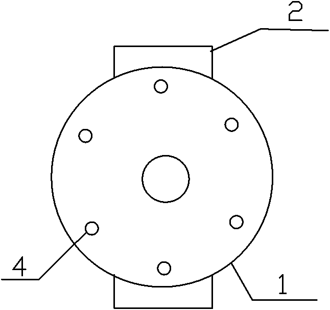
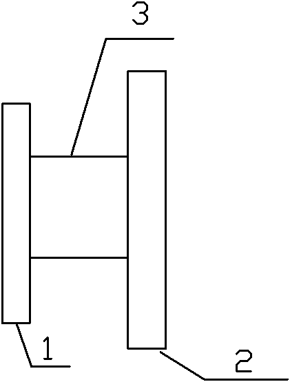
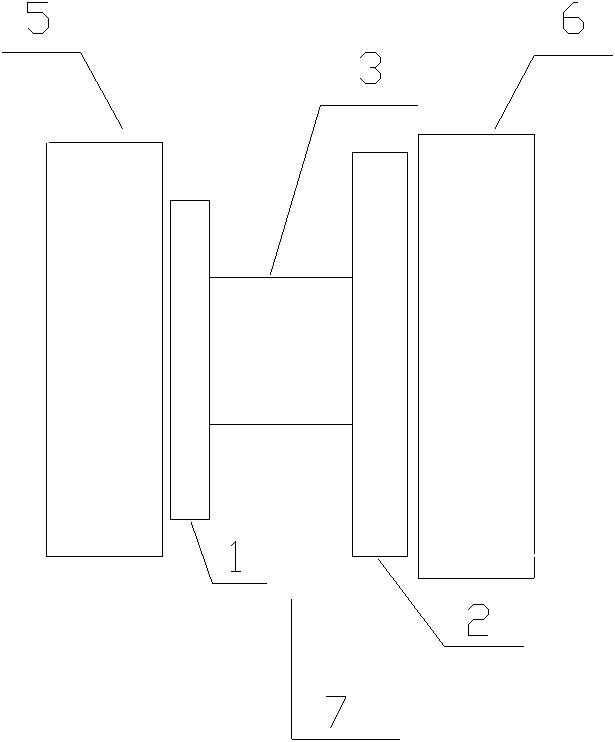
[0014] Such as figure 1 , figure 2 , image 3 As shown, the cooling device is a connection device 7 provided between the cylinder, the oil cylinder 5 and the high-temperature device 6 in contact with it, that is, the mold end. The connection device 7 includes a connection block 1, a base 2 and a connection column 3 , the connecting block 1 and the base 2 are connected through the connecting column 3 . The connecting block 1 is provided with six mounting holes 4 .

[0015] When the present invention is in use, the cooling device, that is, the connecting block 1 of the connecting device 7, is connected to the cylinder or oil cylinder 5, and the base 2 is connected to the high-temperature device 6, that is, the mold end, and the heat of the mold is first transferred to the cooling device, and then to the cylinder Or oil cylinder, the cooling ...


PUM


Abstract

The invention discloses a temperature reducing device for an air cylinder and an oil cylinder. The temperature reducing device is a connecting device arranged between the air cylinder and high temperature equipment in contact with the air cylinder or between the oil cylinder and high temperature equipment in contact with the oil cylinder; the connecting device comprises a connecting block, a base and a connecting column; and the connecting block is connected with the base through the connecting column, wherein at least one installing hole is arranged on the connecting block. The temperature reducing device provided by the invention is used between the air cylinder or oil cylinder and a die, so as to reduce high temperature of the air cylinder or the oil cylinder due to direct contact with the die during the production process; after the temperature reducing device is applied, the temperature at a piston rod of the air cylinder is reduced to around 120 DEG C, the temperature at an oil seal for a shaft of the air cylinder is reduced to around 115 DEG C, the temperature at the a piston rod of the oil cylinder is reduced to 135 DEG C and the temperature at an oil seal for a shaft of the oil cylinder is reduced to 115 DEG C; therefore, the problems of short production time or production failure of the air cylinder and oil leakage of the oil cylinder due to the high temperature are solved, the production efficiency is improved, the production cost is saved, and the service life of the air cylinder or the oil cylinder is prolonged.

Description

technical field [0001] The invention relates to the field of power machinery, in particular to a cooling device used during the use of a cylinder or an oil cylinder. Background technique [0002] In the actual production process of the cylinder and the oil cylinder, the temperature of the other end in contact with it is relatively high. For example, in the mold production process, the temperature of the center of some molds reaches 280 ° C; The temperature at the place reaches about 225°C, and the cylinder often cannot withstand such a high temperature for a long time, resulting in a short production time or even no production of the cylinder, which will also reduce the service life of the cylinder; for the casting mold hydraulic cylinder, the core of the mold shaft is connected to the cylinder piston rod The temperature at the center is about 220°C, which will cause oil leakage from the oil cylinder, which will not only increase the production cost, but also be very inconve...

Claims


Application Information

Patent Timeline
IPC IPC(8): F15B21/00
Inventor 顾明其
Owner TAICANG HAIJIA VEHICLE FITTINGS
Learn More