Miniature loudspeaker and preparation method of miniature loudspeaker

A micro-speaker, injection molding technology, applied in the directions of loudspeakers, sensors, electrical components, etc., can solve the problem of low efficiency and achieve the effect of improving production efficiency

Inactive Publication Date: 2016-08-03
DONGGUAN HUAMING COMM EQUIP
View PDF0 Cites 0 Cited by
  • Summary
  • Abstract
  • Description
  • Claims
  • Application Information

AI Technical Summary

Problems solved by technology

The factory generally uses glue to bond or rivet the PCB to the bracket in a certain way,

Method used


Image

  • Miniature loudspeaker and preparation method of miniature loudspeaker

Examples


Example Embodiment

[0014] In the following, the present invention will be further described
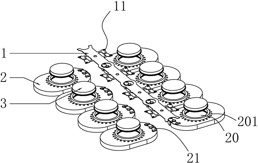
 in conjunction with the embodiments

[0015] As shown in the figure, a miniature speaker includes a plastic bracket 2 and a magnetic circuit system, a voice coil, a diaphragm, and a pad 11 for electrical connection fixed on the plastic bracket.

[0016] Among them, the magnetic circuit system includes a U cup 3 fixed to the plastic bracket 2, a magnetic steel fixed in the U cup 3, and a washer attached to the magnetic steel. The magnetic circuit system is used to provide a magnetic field, and the voice coil is electrically connected through the pad. After being energized, under the action of the magnetic field generated by the magnetic circuit system, it is driven by the Lorentz force to move up and down, and further drives the diaphragm to vibrate and produce sound. The plastic bracket is a flat structure with a sound hole 20 in the center, the U cup 3 is arranged in the center of the plastic bracket 2, and t...


PUM

PropertyMeasurementUnit
Thicknessaaaaaaaaaa

Abstract

The invention discloses a micro-speaker and a preparation method of the micro-speaker. Tin-plated steel sheets are embedded in the PCB of the bracket to replace the externally pasted PCB. No matter whether tin welding or machine spot welding is used, the welding effect can be improved. And efficiency are more than external PCB. It can effectively improve the welding performance of the product, which is beneficial to the mass production of the product and improves the production efficiency.

Description

technical field [0001] The invention belongs to the field of supporting molds for production technology, and specifically refers to a plastic bracket type micro-speaker and a preparation method of the micro-speaker. Background technique [0002] The PCB of the speaker is a simple, cheap but indispensable part of the structure of the speaker, which plays the role of connecting the internal voice coil and the external electronic wire. Factories generally use glue to bond or rivet the PCB to the bracket in a certain way, which requires a certain amount of equipment and manpower, and the efficiency is not high. [0003] Therefore, in order to solve the above problems, the present invention provides a micro-speaker and a preparation method thereof, which are used to improve the welding performance between the micro-speaker and the PCB board. Contents of the invention [0004] Aiming at the deficiencies of the prior art, the invention provides a micro-speaker and a prepar...

Claims


Application Information

Patent Timeline
IPC IPC(8): H04R9/06H04R9/02H04R31/00
CPCH04R9/06H04R9/02H04R31/00H04R2231/00H04R2400/11
Inventor 邓亚中
Owner DONGGUAN HUAMING COMM EQUIP
Why Eureka
Try Eureka