Electronic light emitting device capable of simulating real flame

A light-emitting device, the technology of simulating real fire, applied in the direction of electric light source, electric light source, lighting device, etc., can solve the problems such as the visual experience is not real enough, the difference is big, etc., to achieve the effect of realistic effect and enhance the visual experience

Inactive Publication Date: 2012-10-17
李晓锋
View PDF5 Cites 49 Cited by
  • Summary
  • Abstract
  • Description
  • Claims
  • Application Information

AI Technical Summary

Problems solved by technology

The light-emitting part of this type of electronic light-emitting device tries to simulate the light-emitting form of a candle or kerosene lamp, simulating the flickering, flickering and dimming of the light, but compared with the real flame lit by a real candle or kerosene lamp, there is a big difference. The experience is not real enough

Method used


Image

  • Electronic light emitting device capable of simulating real flame
  • Electronic light emitting device capable of simulating real flame
  • Electronic light emitting device capable of simulating real flame

Examples


Embodiment 1

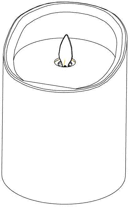
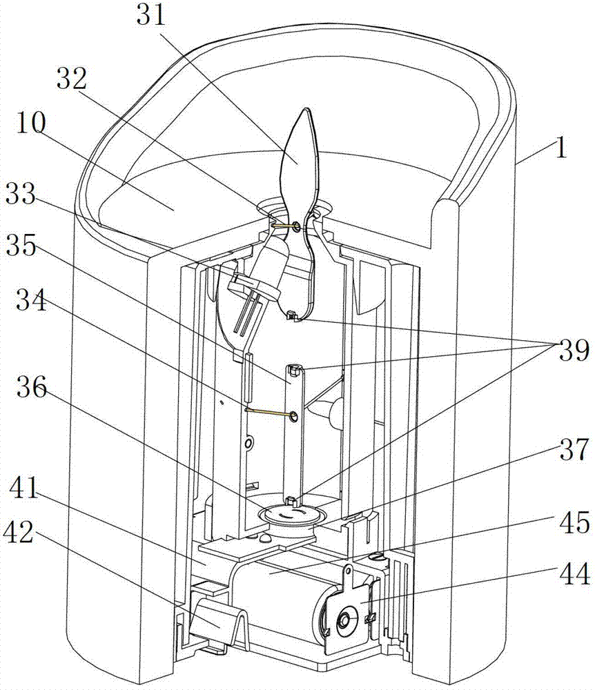
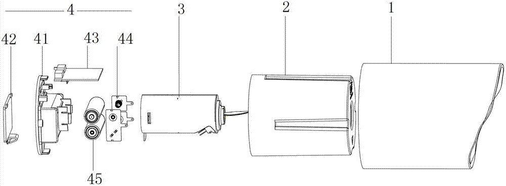
[0031] The specific product in this embodiment is an electronic candle, please combine figure 1 , figure 2 , image 3 , Figure 4 and Figure 5 as shown, figure 1 It is a schematic diagram of the appearance of the electronic candle in this example, which simulates the shape of the candle as a whole, including: a shell 1; a shell 2, which is set in the shell 1; There is a housing through hole in the middle of the top of the housing 2, and a flame piece is arranged therein. The part of the flame piece protruding from the housing through hole is simulated as the wax flame when a candle is lit, and the light emitted by the light-emitting element on the movement Projected at a certain angle on the part where the flame piece protrudes from the through hole, and the flame piece can sway freely under the action of the natural wind or the swing mechanism installed in the movement, so that it looks like a flame from a certain distance. The real candle flame flickers and dances so ...

Embodiment 2

[0045] Please refer to Figure 8 As shown, in this example, the swinging mechanism of Embodiment 1 is subtracted, and the linkage piece 35 part in the middle is canceled, and the coil 37 is close to the lower end of the flame piece 31, and the magnet polarity at the lower end of the flame piece 31 is generated by the coil 37. The different magnetic fields make the two repel each other, and the flame sheet 31 can also keep shaking.

Embodiment 3

[0047] In this example, the structure of this example is adopted for the swing mechanism of the movement 3 in Embodiment 1, please refer to Figure 9 As shown, it includes a hanging rope 301, a swing block 302, a rotating block 303, a motor fixing block 304 and a motor 305; The motor fixing block 304 is fixed in the casing of the movement, and the rotating block 303 is fixedly connected to the output shaft of the motor 305; in the natural state (only under the action of its own gravity, not under the action of external force), the swinging block 302 hangs by its own weight On the hanging rope 301, the lower end of the swinging block 302 contacts the rotating block 303; when the motor 305 is driven, the rotating block 303 will continuously collide with the swinging block 302, and the non-stop shaking of the swinging block 302 will drive the flame sheet 31 to shake disorderly .

[0048] Please refer to Figure 10 Shown is the schematic diagram of the circuit in this example. T...


PUM


Abstract

The invention discloses an electronic light emitting device capable of simulating real flame. The electronic light emitting device comprises a shell, a light emitting element, a flame sheet, a fan and a main PCB (Printed Circuit Board); a shell through hole is arranged at the top of the shell; the flame sheet is movably supported or suspended on the shell and comprises an upper sheet capable of simulating a flame shape, and the upper sheet is exposed at the top of the shell by the shell through hole; the light emitting element is obliquely arranged on the side wall of the shell or in the shell; the light emergency direction of the light emitting element is upward obliquely extended and crossed with the surface of the upper sheet by the shell through hole, so as to enable the light of the light emitting element to be projected on the surface of the upper sheet; the fan is arranged under the flame sheet, and the air outlet direction of the fan is opposite to the flame sheet; and the main PCB is electrically connected with the light emitting element and the fan respectively. The flame sheet shakes under the action of the fan, and light emitted by the light emitting element is projected on the flame sheet, which seems like a real flame swaying, so that the flame simulated by the device is vivid.

Description

technical field [0001] The invention relates to an electronic light emitting device. Background technique [0002] In daily life, various electronic light-emitting devices are widely used in toys, home decoration products, and gifts. For example, people originally regarded candles, kerosene lamps, etc. as lighting fixtures, but with the widespread use of electric light sources, their lighting functions have gradually faded, and people's demand for candles, kerosene lamps, etc. has also changed from practicality to ornamental or Interesting, so various electronic lighting devices such as electronic flashing candles, electronic candles, simulation candles and simulation kerosene lamps have also emerged at the historic moment. The light-emitting part of this type of electronic light-emitting device tries to simulate the light-emitting form of a candle or kerosene lamp, simulating the flickering, flickering and dimming of the light, but compared with the real flame lit by a rea...

Claims


Application Information

Patent Timeline
Patent Type & Authority Applications(China)
IPC IPC(8): F21S10/04F21V14/00H05B37/02F21Y101/02
CPCF21S10/046F21W2121/00
Inventor 李晓锋
Owner 李晓锋
Why Eureka
Try Eureka