Supercharge Your Innovation With Domain-Expert AI Agents!

Lens module

A technique for lens modules and recessed parts, applied in the directions of installation, optics, instruments, etc., can solve problems such as the inability to achieve the goal of being thin and light, and the thickness of the lens module 10 is limited, and achieve the effect of reducing the overall height and volume.

Inactive Publication Date: 2014-09-10
ASIA OPTICAL CO INC
View PDF8 Cites 0 Cited by
  • Summary
  • Abstract
  • Description
  • Claims
  • Application Information

AI Technical Summary

Problems solved by technology

[0004] Due to the need to take into account the strength of the fixed cylinder 11, the fixed cylinder 11 needs a certain thickness, such as figure 1 As shown, this thickness is the distance D1 from the upper surface 113 to the inner surface 114 of the fixed cylinder 11 (hereinafter referred to as the first length D1); in addition, the distance from the top surface 132 to the bottom surface 133 of the long tooth portion 13 is defined as the second length D2, and the distance from the upper surface 113 of the fixed cylinder 11 to the bottom surface 133 of the long tooth portion 13 is defined as the third length D3, as figure 1 As shown, the sum of the first length D1 and the second length D2 is equal to the third length D3; since the thickness of the fixed barrel 11 (namely the first length D1) must maintain a specific length, the known thickness of the lens module 10 will be Restricted, unable to achieve frivolous goals

Method used


Image

  • Lens module
  • Lens module
  • Lens module

Examples


Embodiment Construction

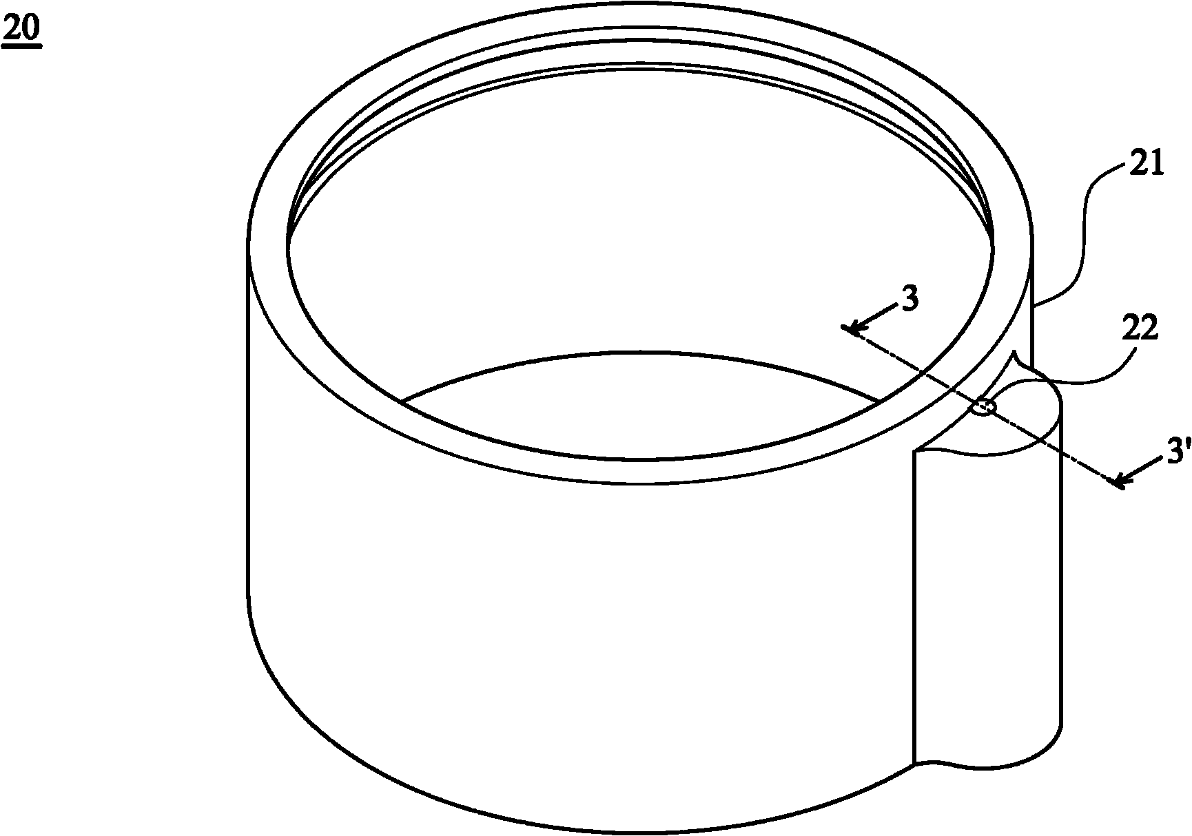
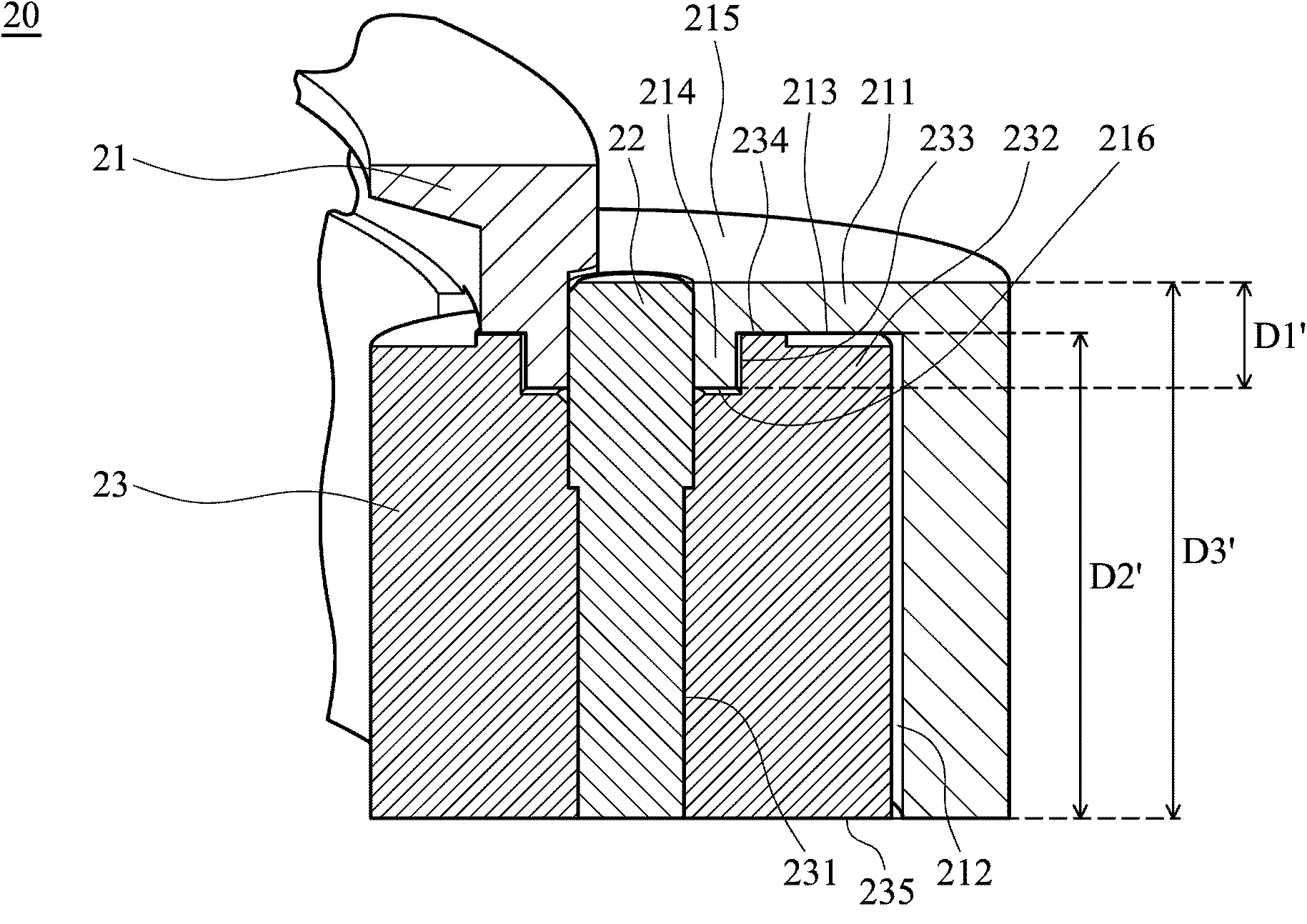
[0015] figure 2 It is a schematic diagram of a lens module according to an embodiment of the present invention. image 3 for along figure 2 The schematic cross-section of the line 3-3'.

[0016] see figure 2 , 3 The lens module 20 includes a fixed cylinder 21, a guide shaft 22, and a long tooth portion 23. The fixed cylinder 21 includes a housing 211, an accommodating groove 212, a first concave portion 213, and a first relative protruding portion 214. The housing 211 forms an accommodating The groove 212 includes an upper surface 215 and an inner surface 216 . In this embodiment, the first concave portion 213 and the first relative protruding portion 214 are arranged adjacent to each other.

[0017] The guide shaft 22 extends from the upper surface 215 of the housing 211 to the accommodating groove 212, and is located in the accommodating groove 212. The long tooth portion 23 includes a positioning groove 231, a second relative protruding portion 232, a second concave ...


PUM


Abstract

The invention relates to a lens module, which includes a fixed cylinder, a long tooth portion and a guide shaft. The fixed cylinder includes a housing and an accommodating groove. The housing forms the accommodating groove and includes an upper surface and an inner surface. The long tooth portion includes a positioning groove, On the top surface and the bottom surface, the long tooth part is placed in the accommodating groove, the guide shaft is set in the positioning groove, the distance from the upper surface to the inner surface of the fixed cylinder is the first length, and the distance from the top surface to the bottom surface of the long tooth part is the second Two lengths, and the distance from the upper surface of the fixed cylinder to the bottom surface of the long teeth is defined as the third length, and the sum of the first length and the second length is greater than the third length.

Description

technical field [0001] The invention relates to a lens module, in particular to a lens module provided with long teeth for driving. Background technique [0002] figure 1 is a schematic cross-sectional view of a known lens module. [0003] see figure 1 , the known lens module 10 includes a fixed cylinder 11, a guide shaft 12, and a long tooth portion 13, the fixed cylinder 11 includes a housing 111 and an accommodating groove 112, the housing 111 includes an upper surface 113 and an inner surface 114, and the guide shaft 12 is located in the housing. Placed in the groove 112, the long tooth part 13 includes a positioning groove 131, a top surface 132 and a bottom surface 133, the long tooth part 13 is placed in the accommodating groove 112 and the guide shaft 12 is placed in the positioning groove 131, so the long tooth part 13 can be placed along the Rotate along the guide shaft 12 to drive the lens. [0004] Due to the need to take into account the strength of the fixe...

Claims


Application Information

Patent Timeline
Patent Type & Authority Patents(China)
IPC IPC(8): G02B7/02
Inventor 黄伟民薛春育黄敦揆
Owner ASIA OPTICAL CO INC
Features
  • R&D
  • Intellectual Property
  • Life Sciences
  • Materials
  • Tech Scout
  • Unparalleled Data Quality
  • Higher Quality Content
  • 60% Fewer Hallucinations
Learn More