
Control method and system of vehicle emergency signal light

A technology for signal light control and vehicle controller, applied in optical signals, signal devices, vehicle components, etc., can solve the problems of complicated operation, many operation steps, increase the probability of vehicle accidents, etc., and achieve extended use time and easy operation. Effect

Active Publication Date: 2014-12-10
XUZHOU HEAVY MASCH CO LTD
View PDF7 Cites 0 Cited by
  • Summary
  • Abstract
  • Description
  • Claims
  • Application Information

AI Technical Summary

Problems solved by technology

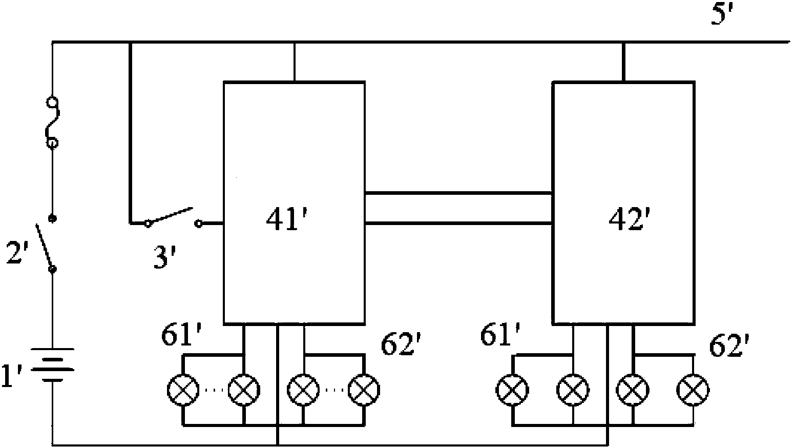
[0006] When the vehicle encounters a critical situation, although only the left turn signal group 61' and the right turn signal group 62' need to work at this time, in the above-mentioned existing emergency signal light control system, once the key switch 2' is closed, other electrical components will still remain. conduction; if the vehicle encounters a critical time for a long time, the conduction of too many on-board electrical components will accelerate the depletion of battery 1'. Increased probability of vehicle accidents
[0007] In addition, the prerequisite for the operation of the emergency signal light is that the key switch 2' and the emergency signal light switch 3' are closed at the same time, so there are many operating steps and the operation is cumbersome.

Method used


Image

  • Control method and system of vehicle emergency signal light
  • Control method and system of vehicle emergency signal light
  • Control method and system of vehicle emergency signal light

Examples


Embodiment Construction

[0034] In order to enable those skilled in the art to better understand the technical solutions of the present invention, the present invention will be further described in detail below in conjunction with the accompanying drawings and specific embodiments.

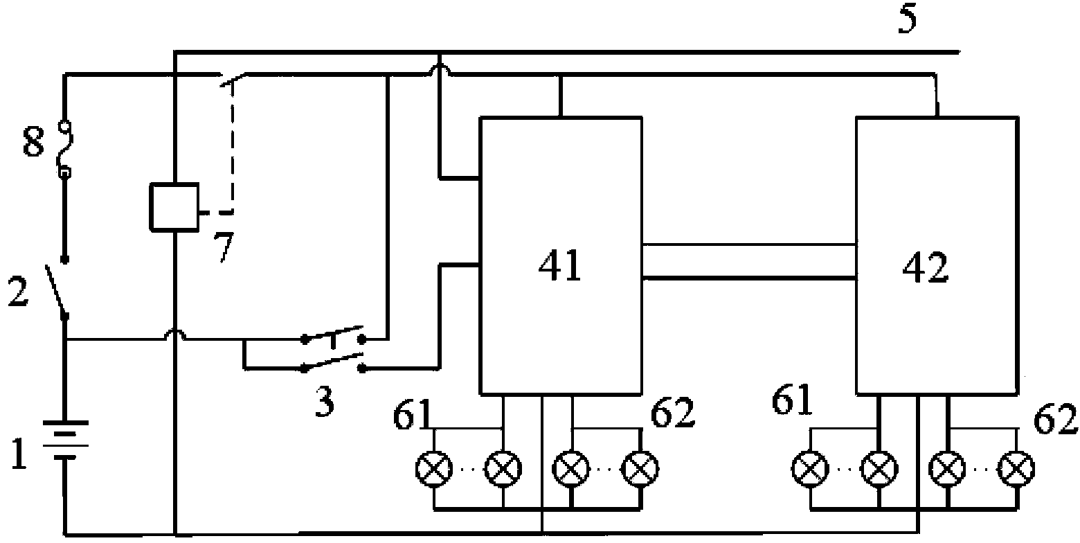
[0035] Please see image 3 , image 3 It is a schematic diagram of the principle of a vehicle emergency signal light control system provided by a specific embodiment of the present invention.

[0036] Such as image 3 As shown, the present invention provides a vehicle emergency signal light control system, including a power supply, an emergency signal light switch 3 and a key switch 2. In a specific solution, the power supply can be a battery 1, and the emergency signal light switch 3 forms a The first circuit, the key switch 2 forms a second circuit with electrical components of the vehicle except the signal lights, and the first circuit and the second circuit are connected in parallel to the power supply.

[0037] Wh...


PUM


Abstract

The invention relates to the field of vehicle electric control technology, and discloses a control system of a vehicle emergency signal light. The control system comprises a power supply, an emergency signal light switch and a key switch, wherein the emergency signal light switch and an emergency signal light of a vehicle are formed to be a first loop; all the electric elements of the vehicle, except for the emergency signal light, and the key switch are formed to be a second loop; and the first loop and the second loop are connected in parallel to the power supply. With the adoption of the control system of the vehicle emergency signal light, the circuit consumption of other vehicle-mounted electric elements can be reduced, and the service time of the power supply of a vehicle-mounted storage battery can be prolonged in emergency. And the invention also discloses a control method of the vehicle emergency signal light.

Description

technical field [0001] The invention relates to the technical field of vehicle electrical control, in particular to a vehicle emergency signal light control system, and also relates to a vehicle emergency signal light control method. Background technique [0002] When the vehicle encounters a critical situation, the driver of the vehicle needs to turn on the emergency signal light switch to alert other road users. There are two conventional control methods for the emergency signal lights of traditional super-large vehicles, one is to use flashing relays; the other is to use programmable logic controllers. [0003] With the continuous development of automotive electrical technology, the current emergency signal control mainly adopts the method of programmable controller. The principle of this method is as follows: figure 1 As shown, this vehicle emergency signal light control system generally includes a battery 1', a key switch 2', an emergency signal light switch 3', and a ...

Claims


Application Information

Patent Timeline
Patent Type & Authority Patents(China)
IPC IPC(8): B60Q1/52
Inventor 朱长建任卫军朱林赵忠祥齐行程赵欢
Owner XUZHOU HEAVY MASCH CO LTD
Learn More