
Apparatus and method for checking at least one solder joint between a printed circuit board and a current sensor

A technology of current sensor and welding part, which is applied in the direction of adopting electrical devices, voltage/current isolation, measuring devices, etc., can solve the problems of increasing production costs, and achieve the effect of saving circuit consumption and saving external processors

Pending Publication Date: 2021-03-05
INFINEON TECH AG
View PDF0 Cites 0 Cited by
  • Summary
  • Abstract
  • Description
  • Claims
  • Application Information

AI Technical Summary

Problems solved by technology

Wettable coatings on connectors enable AOI after soldering, but also increase production costs

Method used


Image

  • Apparatus and method for checking at least one solder joint between a printed circuit board and a current sensor
  • Apparatus and method for checking at least one solder joint between a printed circuit board and a current sensor
  • Apparatus and method for checking at least one solder joint between a printed circuit board and a current sensor

Examples


Embodiment Construction

[0026] Various examples will now be described more fully with reference to the accompanying drawings in which some examples are shown. In the drawings, the thickness of lines, layers and / or regions may be exaggerated for clarity.

[0027] Therefore, while further examples are capable of various modifications and alternative forms, some specific examples thereof are shown in the drawings and described in detail later. However, this detailed description does not limit the additional examples to the specific forms described. Additional examples may cover all modifications, equivalents, and alternatives falling within the scope of the disclosure. Like reference numerals denote like or similar elements in the description of the figures, which when compared to each other may be implemented in the same or in a modified form, while providing the same or similar functions.

[0028] It will be understood that when an element is referred to as being "connected" or "coupled" to another ...


PUM


Abstract

The present disclosure relates to a concept for checking at least one solder joint between a printed circuit board and a current sensor, including: measuring, by means of the current sensor, an electric current through the solder joint; measuring at least one temperature of the current sensor as a function of the electric current; and ascertaining a quality of the solder joint based on the temperature and the electric current.

Description

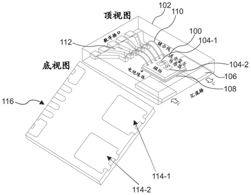
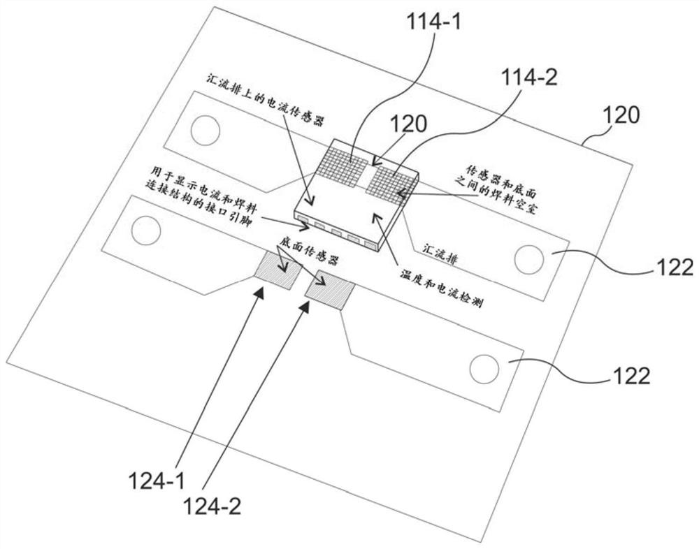
technical field [0001] The present disclosure relates to an apparatus and method for inspecting at least one solder joint between a circuit board and a current sensor. Background technique [0002] Electrical measurements are receiving increasing attention through the electrification of the automotive sector and industrial automation. Especially for applications requiring high power density, current sensors that can be easily mounted on printed circuit boards are required. In constructions where the current sensor is soldered to a printed circuit board, the solder joint quality must be as good as possible to avoid power losses due to eg poor electrical conductivity between the busbar and the current sensor. [0003] Therefore, good electrical conductivity and cavity-free solder joints are important to ensure an additional resistance as low as possible. Poor welds with cavities can affect the accuracy and sensitivity of the current sensor. Typical current ranges for low-oh...

Claims


Application Information

Patent Timeline
IPC IPC(8): G01R15/20G01R19/25G01K7/00
CPCG01R15/20G01R15/202G01R15/205G01R19/25G01K7/00G01R15/207G01R35/00G01R31/71G01R31/2879G01R31/2874G01R33/07G01R31/2815G01N33/207G01N27/041G01N27/046
Inventor T·克兰兹
Owner INFINEON TECH AG
Learn More