Supercharge Your Innovation With Domain-Expert AI Agents!

Variable-stage or variable-cylinder variable displacement compressor and control method thereof

A compressor and variable displacement technology, which is applied in the field of compressors, can solve the problems of not being able to pull, increase the power consumption of the top slide, and restrict the application and development of frequency conversion technology, so as to achieve the goal of increasing the high-temperature cooling capacity and improving the advantages of heating capacity Effect

Inactive Publication Date: 2012-10-24
GREE ELECTRIC APPLIANCES INC +1
View PDF7 Cites 5 Cited by
  • Summary
  • Abstract
  • Description
  • Claims
  • Application Information

AI Technical Summary

Problems solved by technology

It is feasible under ideal conditions, but in actual work, due to the high-speed operation of the compressor, it is often not in place or cannot be pulled, and the power consumption of the top slide increases.
At present, high efficiency, energy saving and comfort are the goals constantly pursued by the air conditioning industry, and the inverter compressor was born. However, the inverter compressor has problems of difficult control and high cost, which restricts the application and development of inverter technology.

Method used


Image

  • Variable-stage or variable-cylinder variable displacement compressor and control method thereof
  • Variable-stage or variable-cylinder variable displacement compressor and control method thereof
  • Variable-stage or variable-cylinder variable displacement compressor and control method thereof

Examples


Embodiment Construction

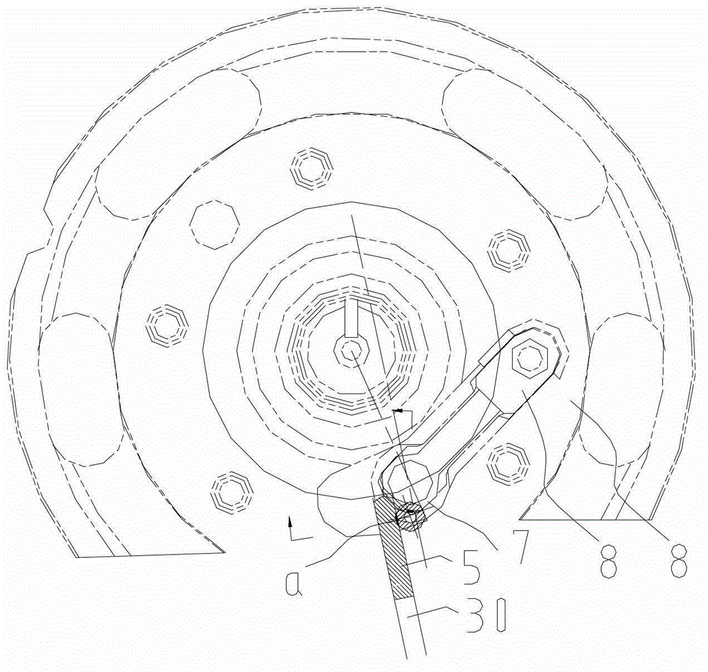
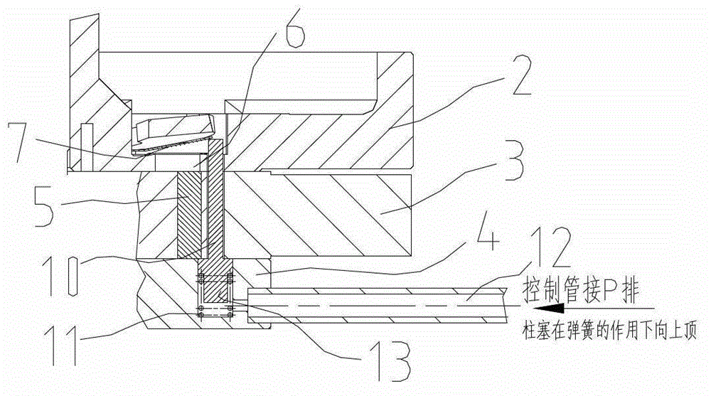
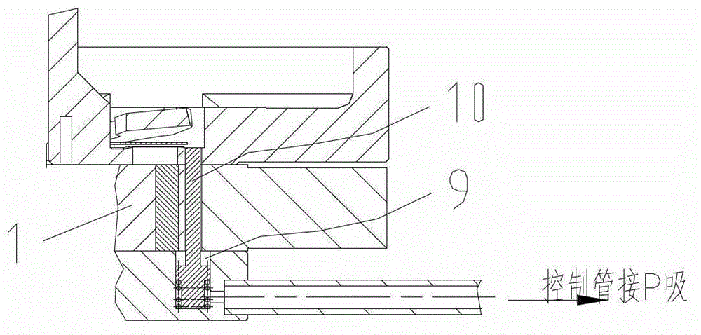
[0021] A variable-stage or variable-cylinder variable-displacement compressor, such as Figure 1 to Figure 3 As shown, it includes crankshaft (not shown in the figure), upper roller 1, lower roller (not shown in the figure), upper flange 2, upper cylinder 3, separator 4, lower cylinder (not shown in the figure) and lower Flange (not shown in the figure), the upper and lower rollers are respectively installed on the crankshaft and rotate in the upper and lower cylinder chambers, the cylinder wall of the upper cylinder 3 is provided with a sliding vane groove 30, and the sliding vane groove 30 is equipped with The upper slide 5 that works in cooperation with the upper roller 1; the upper flange 2 is provided with an exhaust hole 6 communicating with the compression working chamber of the upper cylinder 3, and the upper flange 2 is equipped with a plug to block the exhaust hole 6 The valve plate 7 and the baffle plate 8 are provided with a plunger hole 9 on the axial direction of...


PUM


Abstract

The invention discloses a variable-stage or variable-cylinder variable displacement compressor. The compressor comprises a crankshaft, an upper roller, a lower roller, an upper flange, an upper cylinder, a separation board, a lower cylinder and a lower flange, wherein the upper flange is provided with a gas vent communicated with the compression working chamber of the upper cylinder; the upper flange is provided with a valve blade and a separation blade which are used for sealing the gas vent; a plunger aperture used for communicating the upper flange, the upper cylinder and the separation board and making the three parts be coaxial in the axial direction of the three parts; an inverted T-shaped plunger is arranged in the plunger aperture; the lower end of the plunger is connected with a spring arranged in the plunger aperture at the separation board; the radial wall rim communication position of the separation board at the side surface of the tail end of the plunger aperture is provided with a control tube which is selectively communicated with a high pressure gas at the gas discharge port of the compressor and a low pressure gas at the gas suction port of the compressor respectively; and the up-and-down reciprocating motion of the plunger in the plunger aperture is controlled by the high pressure gas or the low pressure gas in the control tube to jack up the valve blade to the separation blade to control a high pressure refrigerant in the upper cylinder to be directly discharged through the gas vent of the upper flange. The invention also discloses a method for controlling the variable-stage or variable-cylinder variable displacement of the compressor.

Description

【Technical field】 [0001] The invention relates to the field of compressors, in particular to a compressor with variable stages or variable cylinders and variable displacement and a control method thereof. 【Background technique】 [0002] The current compressors include single-stage compressors and two-stage compressors. Commonly used single-unit compressors can meet the energy efficiency requirements of refrigeration, while two-stage compressors have advantages in heating, but the power in cooling is relatively high, which exceeds the range of energy efficiency. There is an urgent need for a compressor that can be directly converted between a single-stage compressor and a two-stage compressor, and has the functions of heating enthalpy and refrigeration. [0003] Under normal circumstances, the method of changing a two-stage compressor to a single-stage compressor or a two-cylinder compressor to a single-cylinder compressor is to pull up the sliding plate or top the exhaust va...

Claims


Application Information

Patent Timeline
IPC IPC(8): F04C28/24
Inventor 杜俊律
Owner GREE ELECTRIC APPLIANCES INC
Features
  • R&D
  • Intellectual Property
  • Life Sciences
  • Materials
  • Tech Scout
  • Unparalleled Data Quality
  • Higher Quality Content
  • 60% Fewer Hallucinations
Learn More