Intensive bus duct

A busway, intensive technology, applied in the direction of cooling busbar devices, semi-closed busbar devices, etc., can solve the problem that the heat dissipation effect of the joint part does not reach the ideal effect, affects the conductivity of the busbar of the busway product, and is unfavorable for the dynamic and thermal stability of the busbar and other problems, to achieve the effect of heat dissipation, fewer parts and simple product structure

Active Publication Date: 2012-10-24
江苏华鹏电力设备股份有限公司
View PDF7 Cites 2 Cited by
  • Summary
  • Abstract
  • Description
  • Claims
  • Application Information

AI Technical Summary

Problems solved by technology

[0002] According to the existing technology, the intensive busway structure is a combined structure of cover plate and side plate, using the small ribs (fixed parts) on both sides of the upper and lower cover plates to hold the left and right side plates at the same time, and the cover plate and side plate punching holes are fixed by bolts. Although this structure can connect the side cover plates of the busbar, the bolt fixing is not conducive to the dynamic and thermal stability of the busbar, resulting in a high temperature of the busbar during operation, which affects the conductivity of the busbar of the busway product; and the installation of the existing dense busway , the number of bolts required is large, and the installation process is cumbersome, which affects the efficiency of production and installation, and because of the high cost of bolts, it affects the economic benefits of the product
The existing busbar socket structure adopts the traditional structure, and the pin assembly is riveted on both sides of the busbar with riveting equipment. The product assembly process is cumbersome. Although the joint part of the busbar has a heat sink structure, the heat dissipation effect of the joint part is not achieved during normal operation. Ideal effect, high temperature rise, there are certain safety hazards

Method used


Image

  • Intensive bus duct
  • Intensive bus duct
  • Intensive bus duct

Examples


Embodiment Construction

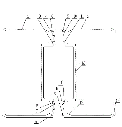
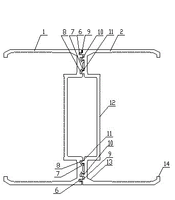
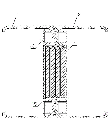
[0016] As shown in the figure, the dense busway of the present invention is composed of a left conjoined side cover plate 1, a right conjoined side cover plate 2, a reinforcing rib sealing plate 3, a bus bar 4 and an insulating layer 5, and the bus bar 4 is covered The insulating layer 5 is then placed in the middle of the left conjoined side cover 1 and the right conjoined side cover 2. The left conjoined side cover 1 and the right conjoined side cover 2 are rolled and riveted by special riveting equipment to form intensive The overall busway, the reinforcing rib sealing plate 3 is fixed on the upper and lower necks of the dense busway integral body composed of the left conjoined side cover plate 1 and the right conjoined side cover plate 2.

[0017] In the dense busway of the present invention, the riveting contact surface of the left conjoined side cover plate 1 has riveting grooves 6, riveting claws 7, and riveting hook grooves 8, and the riveting surface of the right conjo...


PUM


Abstract

The invention relates to an intensive bus duct which comprises a left connecting body side cover plate, a right connecting body side cover plate, reinforcing rib seal plates, a bus bar and an insulation layer; the bus bar is coated with the insulation layer and then is arranged between the left connecting body side cover plate and the right connecting body side cover plate; the left connecting body side cover plate and the right connecting body side cover plate are formed into the whole intensive bus duct by rolling and riveting through special riveting equipment; and the reinforcing rib seal plates are fixedly arranged on the upper neck and the lower neck of the whole intensive bus duct formed by the left connecting body side cover plate and the right connecting body side cover plate. According to the intensive bus duct, the product structure is simple, the number of parts is minimized, the production process is simplified, assembly procedures are simple, the transportation and the installation are convenient, the operation effect is reliable, and the heat dissipation performance is excellent.

Description

technical field [0001] The invention relates to a dense busway in power transmission and transformation equipment in public places, which is applied to distribution networks or industrial devices, large and medium-sized industrial and commercial buildings, airports, shopping malls, lighting and power supply of enterprises, and the like. Background technique [0002] According to the existing technology, the dense busway structure is a combination structure of cover plate and side plate, using the small ribs (fixed parts) on both sides of the upper and lower cover plates to hold the left and right side plates at the same time, and the cover plate and side plate punching holes are fixed by bolts. Although this structure can connect the side cover plates of the busbar, the bolt fixing is not conducive to the dynamic and thermal stability of the busbar, resulting in high temperature of the busbar during operation, which affects the conductivity of the busbar of the busway product...

Claims


Application Information

Patent Timeline
Patent Type & Authority Applications(China)
IPC IPC(8): H02G5/04H02G5/10
Inventor 殷明王庆江华张俊唐云彩戴姚佳
Owner 江苏华鹏电力设备股份有限公司
Why Eureka
Try Eureka