Quick-detachment positioning structure for rail component

A rail component and structure technology, which is applied in the field of quick release positioning structure of rail components, can solve problems such as strengthening the positioning state, damage, and shrapnel deformation that are not specifically proposed

Active Publication Date: 2014-03-26
KING SLIDE WORKS CO LTD
View PDF8 Cites 2 Cited by
  • Summary
  • Abstract
  • Description
  • Claims
  • Application Information

AI Technical Summary

Problems solved by technology

[0006] Obviously, although the aforementioned means can provide the positioning of the rails where the equipment or chassis is installed on the slide rails, there is no special solution to strengthen the positioning state for the problem that the aforementioned shrapnel may be deformed or even damaged

Method used


Image

  • Quick-detachment positioning structure for rail component
  • Quick-detachment positioning structure for rail component
  • Quick-detachment positioning structure for rail component

Examples


Embodiment Construction

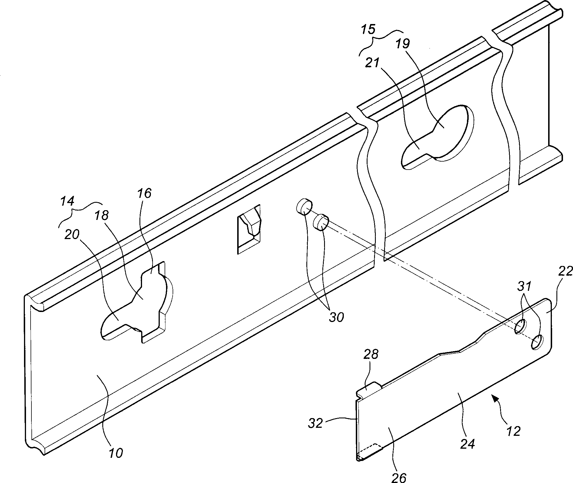
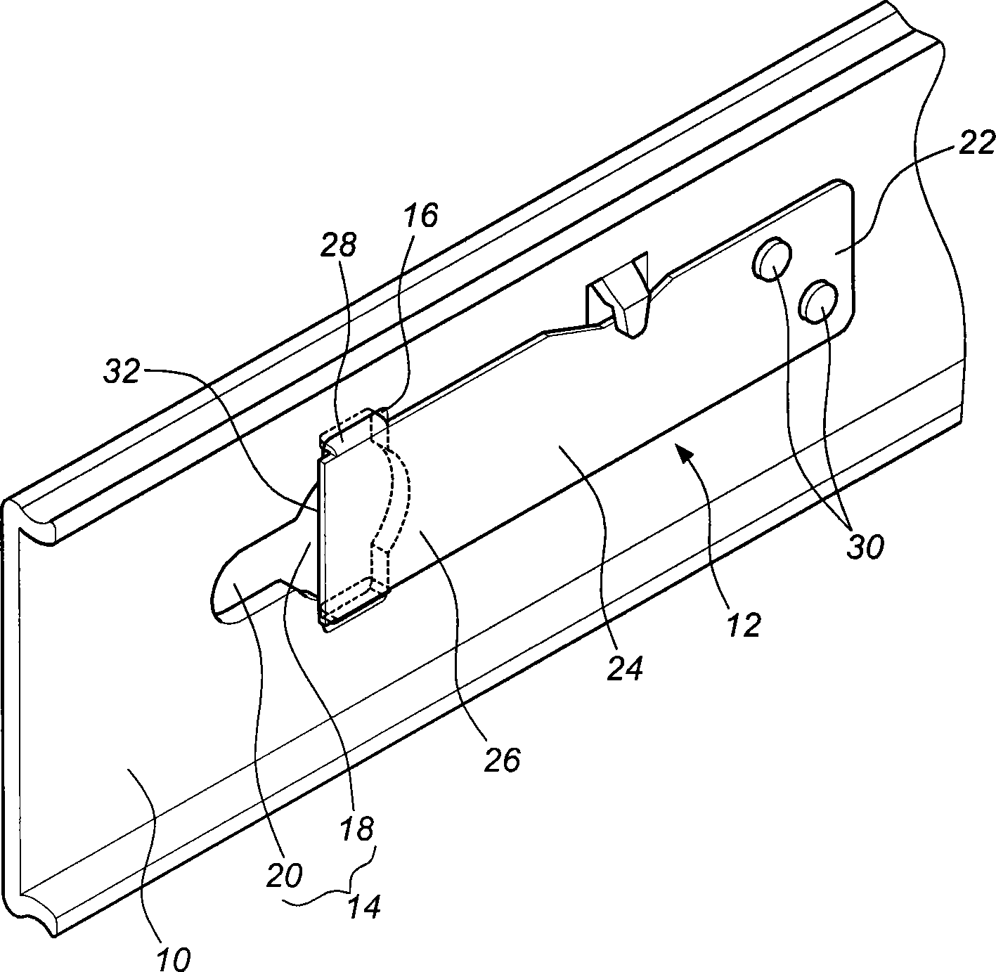
[0027] figure 1 and figure 2 It is shown that the first preferred embodiment of the present invention includes a rail member 10 and a positioning member 12 . in:

[0028] The rail 10 includes at least two openings 14 , 15 and a first resisting portion 16 , wherein the opening 14 includes an opening 18 and a locked portion 20 communicating with the opening 18 . The opening 15 also includes an opening portion 19 and a locked portion 21 communicating with the opening portion 19 . The first resisting portion 16 is adjacent to one of the two openings 14 , 15 , such as the opening 14 . In this embodiment, the openings 18 , 19 are enlarged holes; the locked portion 20 is a narrow hole relative to the opening 18 ; the locked portion 21 is also a narrowed hole relative to the opening 19 .

[0029] The positioning member 12 includes a base portion 22 , an elastic arm 24 , a limiting portion 26 and a second resisting portion 28 . Wherein, the positioning member 12 is fixed to the r...


PUM


Abstract

The invention relates to a quick-detachment positioning structure for a rail component. The quick-detachment positioning structure for the rail component comprises an open hole formed in the rail component and a positioning component corresponding to the open hole, wherein the rail component comprises a first stopping part adjacent to the open hole; the open hole comprises an open part and a clamped part communicated with the open part; the positioning component comprises a base part, an elastic arm, a limiting part and a second stopping part; the base part is connected to the rail component and is positioned; the elastic arm extends from the base part and is connected with the limiting part; the limiting part has a first stopping end corresponding to the clamped part; the second stopping part is connected to the limiting part; and when the first stopping end and the clamped part surround into a locked closed area, the second stopping part props against the first stopping part of the rail component, so that the position of the first stopping end is more steady.

Description

technical field [0001] The invention relates to a quick-release positioning structure of a rail, in particular to a structure for quickly and stably connecting and positioning a device with the rail. Background technique [0002] The prior art is applied to the positioning structure of a rail member that can quickly and stably connect a device to a slide rail, mainly providing a slot in the shape of a keyhole slot on the rail member of the slide rail, and fixing it by means of a shrapnel. Connected to the rail corresponding to the key hole, wherein the key hole includes an enlarged hole and a narrow hole communicating with the enlarged hole, and the elastic sheet extends to the key hole to cover the enlarged hole. When assembling, use the fixed bolt fixed on one side of the device to correspond to the key hole of the rail, and make the fixed bolt inserted into the enlarged hole of the groove and then move toward the narrow hole of the groove, and then use the shrapnel agains...

Claims


Application Information

Patent Timeline
Patent Type & Authority Patents(China)
IPC IPC(8): A47B88/08H05K7/14H05K7/18A47B88/49
Inventor 陈庚金王俊强
Owner KING SLIDE WORKS CO LTD
Why Eureka
Try Eureka