Lubricating pump, pump body and pump cover thereof

A technology of oil pump and pump body, which is applied in the field of oil pumps, can solve problems such as the influence of oil pump flexibility, loss of diesel engine users, and limited positioning strength, and achieve the effects of convenient pump cover positioning, reliable assembly quality, and improved work efficiency

Inactive Publication Date: 2013-01-02
南京腾源机械制造有限公司
View PDF0 Cites 0 Cited by
  • Summary
  • Abstract
  • Description
  • Claims
  • Application Information

AI Technical Summary

Problems solved by technology

However, the positioning strength of the ¢5 cylindrical pin is limited, and accidental collisions and drops during the handling, loading and unloading of the oil pump may cause dislocation of the body and cover, which will affect the flexibility of the oil pump operation, and even cause "dead pump" in serious cases.
Cause damage to the diesel engine and bring losses to the user of the diesel engine

Method used


Image

  • Lubricating pump, pump body and pump cover thereof
  • Lubricating pump, pump body and pump cover thereof
  • Lubricating pump, pump body and pump cover thereof

Examples


Embodiment 1

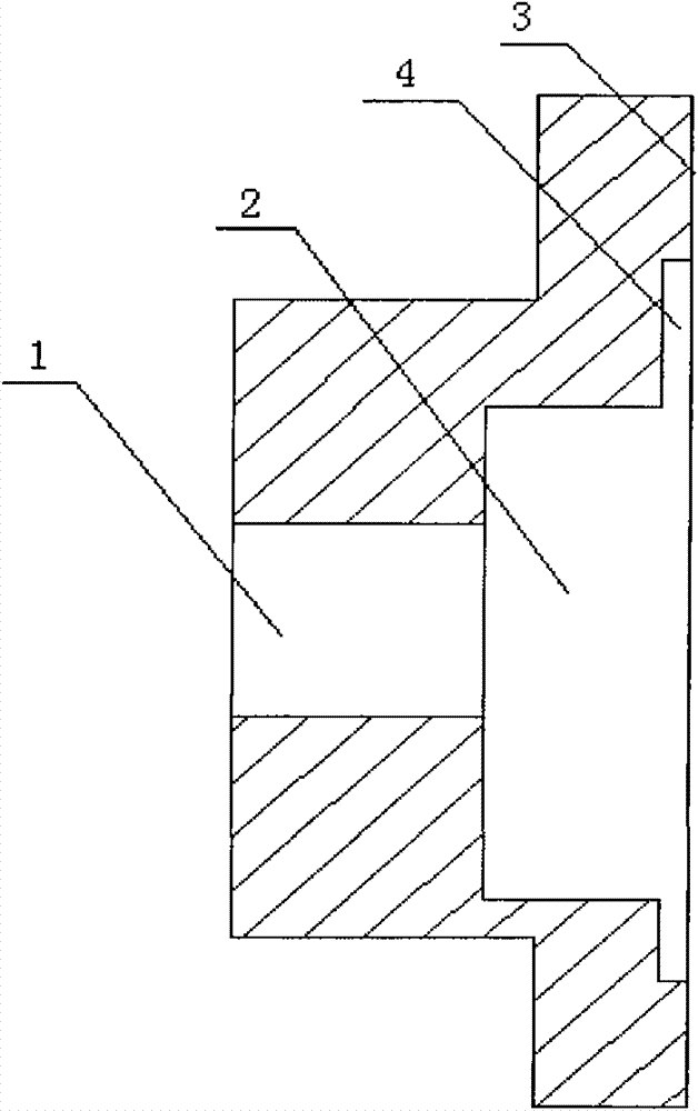
[0017] see figure 1 , an oil pump pump body, including a pump shaft support hole 1, a rotor cavity 2 and a large end surface 3 for installing a pump cover, and the large end surface 3 is recessed radially inward along the rotor cavity 2 to form a stepped hole 4. The specific size of the oil pump body of this machine can be determined according to the actual situation. In this embodiment, the diameter of the rotor chamber 2 is 41mm, the diameter of the step hole 4 is 60mm, and the diameter of the pump shaft support hole 1 is 16mm. When assembling the pump body of the oil pump, the outer edge of the pump cover matching the step hole 4 is embedded in the step hole, and the pump cover and the step hole 4 are transitionally fitted, so the original drilling, reaming, riveting and other processes are cancelled, and the assembly work It is more simple, the assembly speed is greatly improved, and the assembly quality is better. It not only improves the accuracy and positioning strength...

Embodiment 2

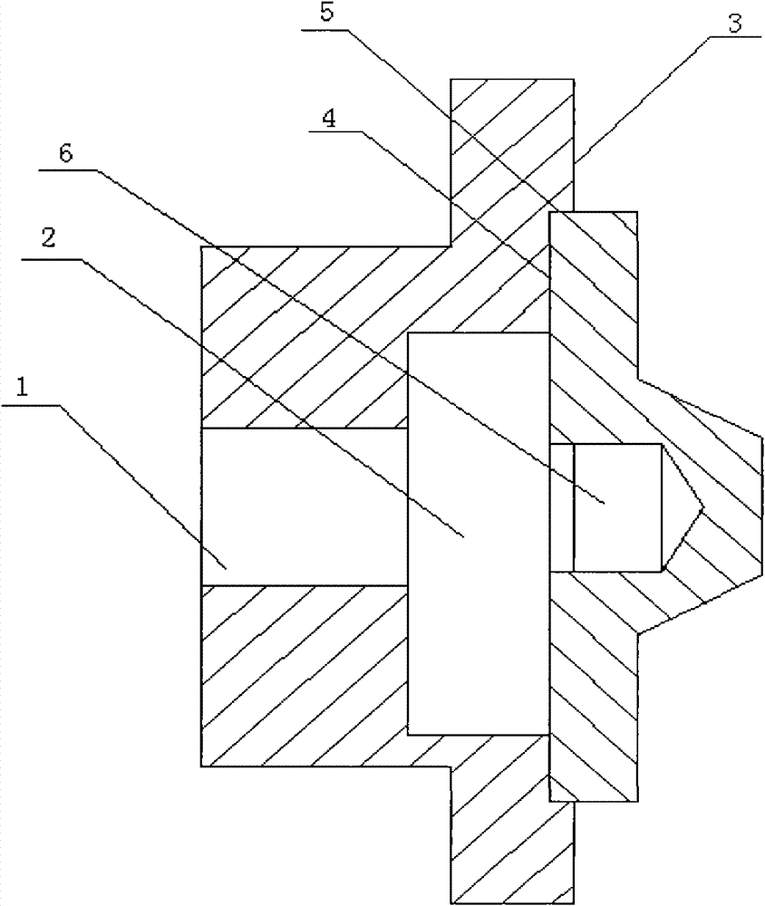
[0019] see figure 2 , an oil pump casing, including a pump body and a pump cover, the pump body is provided with a pump shaft support hole 1, a rotor chamber 2 and a large end face 3 for installing the pump cover, the large end face 3 extends along the diameter of the rotor chamber 2 Inwardly recessed to form a stepped hole 4, the outer edge 5 of the pump cover is embedded in the stepped hole 4 and transitionally fits with the stepped hole 4, the pump cover is provided with a pump shaft end support hole 6, and the pump shaft end support hole 6 , the central axis of the stepped hole 4 and the pump shaft support hole 1 coincide. The support hole 6 at the end of the pump shaft, the step hole 4 and the pump shaft support hole 1 are concentric holes, which further facilitates the positioning of the pump cover, and also makes the positioning of the pump cover more accurate, and the connection between the pump cover and the pump body is firmer; The pump cover is fixed on the pump b...

Embodiment 3

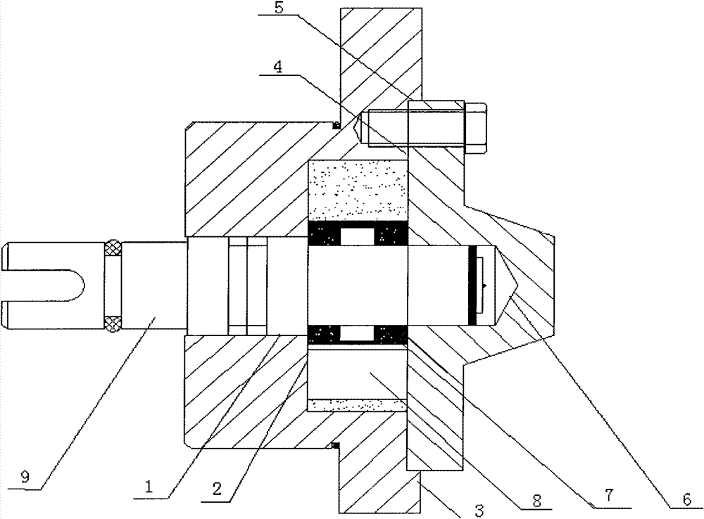
[0021] see image 3 , Figure 4 and Figure 5 , an oil pump, comprising a pump body, a pump cover, an inner rotor 7, an outer rotor 8 and a pump shaft 9, the pump body is provided with a pump shaft support hole 1, a rotor cavity 2 and a large end face 3 for installing the pump cover, The large end face 3 is recessed radially inward along the rotor chamber 2 to form a step hole 4, the pump cover is provided with a pump shaft end support hole 6, the inner rotor 7 and the outer rotor 8 are arranged in the rotor chamber 2, and the edge of the pump cover 5 and the stepped hole 4 transitionally fit and seal the rotor cavity 2, the pump shaft 9 passes through the pump shaft support hole 1 and the end of the pump shaft 9 extends into the pump shaft end support hole 6, and there is also an overflow in the pump shaft 9 The overflow return hole 10 extends axially from the end of the pump shaft 9 away from the pump cover along the pump shaft 9 , and the axial length of the overflow retu...


PUM


Abstract

The invention discloses a pump body of a lubricating pump, comprising a pump shaft support hole, a rotor cavity and a big end surface. The big end surface is used for mounting the pump cover and recesses inwards along the radial direction of the rotor cavity to form stepped-holes. The invention also discloses a pump cover of the lubricating pump, comprising the pump body and the pump cover. The pump cover is embedded into the stepped-holes and matched with the stepped-holes in transition. The invention also discloses a lubricating pump, comprising the pump body, the pump cover, an inner rotor, an outer rotor and a pump shaft. The edge of the pump cover is matched with the stepped-holes in transition and seals the rotor cavity, the pump shaft passes through the pump shaft support hole, theend part of the pump shaft extends into the support hole at the end part of the pump shaft, the pump shaft is also internally provided with an overflow circumfluence hole which extends from one end of the pump shaft far from the pump cover along the radial direction of the pump shaft, and the axial length of the overflow circumfluence hole is shorter than that of the pump shaft. The invention improves the locating accuracy and the locating strength of the pump cover, simplifies the assembling flow, improves the working efficiency, avoids the engine oil leakage phenomenon, and has simple and compact structure and easy implementation.

Description

technical field [0001] The present invention relates to an engine oil pump body, an engine oil pump casing including the above engine oil pump body and an engine oil pump. Background technique [0002] The oil pump is the core component of the diesel engine lubrication system. The single-cylinder diesel engine oil pumps produced in my country generally use the rotor-type oil pump, which is mainly composed of a pump body, a pump cover, an inner rotor, an outer rotor, a pump shaft, and positioning pins. The balance shaft in the diesel engine drives the pump shaft of the oil pump to rotate, and the rotation of the pump shaft causes the volume between the inner and outer rotor teeth to change cyclically, realizing the function of oil suction and oil discharge of the oil pump. Long-term practice has proved that the assembly quality of the oil pump directly affects the performance of the oil pump. Therefore, the technical quality requirements of the production workers of the oil...

Claims


Application Information

Patent Timeline
Patent Type & Authority Patents(China)
IPC IPC(8): F04C2/10
Inventor 邢小军魏水源
Owner 南京腾源机械制造有限公司
Why Eureka
Try Eureka