Variable geometry turbocharger

A turbocharger and capacity technology, applied in the direction of machines/engines, engine components, internal combustion piston engines, etc., can solve the problems of turbine efficiency reduction, exhaust gas disorder, etc., and achieve the effect of stable operation and simple structure

Active Publication Date: 2012-10-31
IHI CORP
View PDF7 Cites 14 Cited by
  • Summary
  • Abstract
  • Description
  • Claims
  • Application Information

AI Technical Summary

Problems solved by technology

Therefore find: the exhaust gas with high pressure flows to the downstream of the exhaust nozzle 9 through the gap between each nozzle vane 15 and the rear exhaust introduction wall 11, due to the flow of the exhaust gas, the exhaust gas at the outlet of the turbine wheel 4 is greatly reduced. Turbulence, due to which the efficiency of the turbine is reduced

Method used


Image

  • Variable geometry turbocharger
  • Variable geometry turbocharger
  • Variable geometry turbocharger

Examples


Embodiment Construction

[0037] Hereinafter, embodiments of the present invention will be described with reference to the drawings.

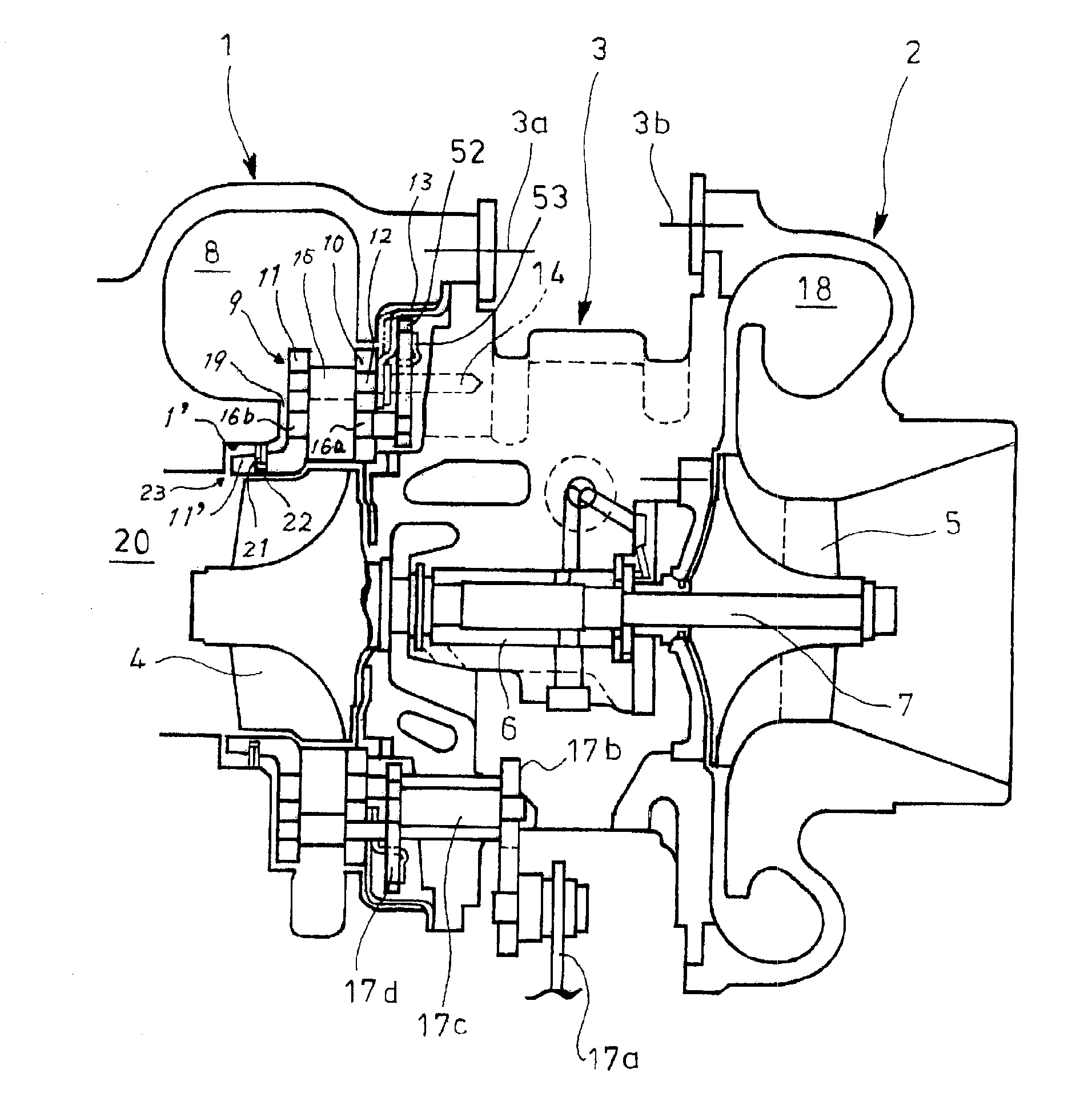
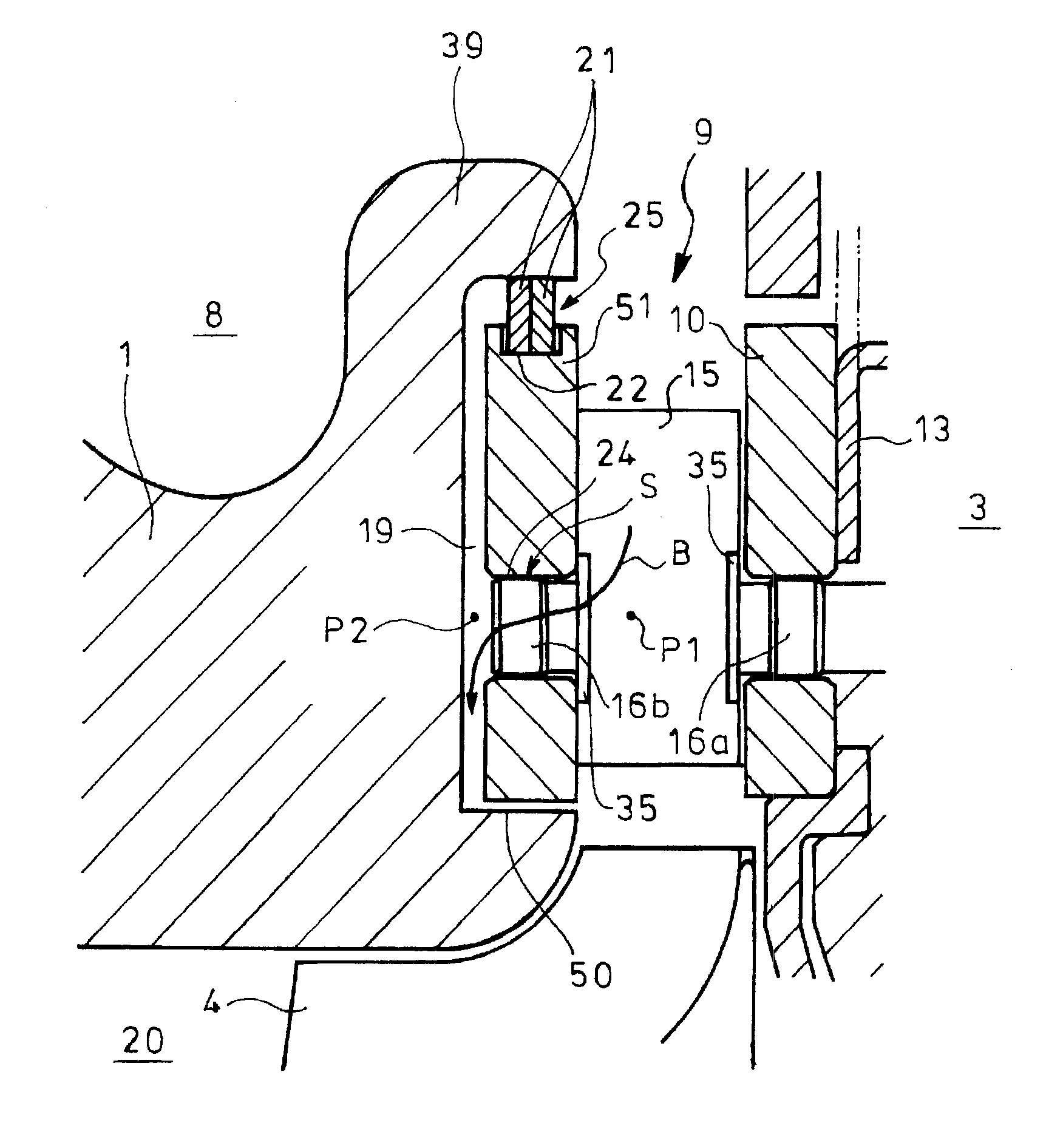
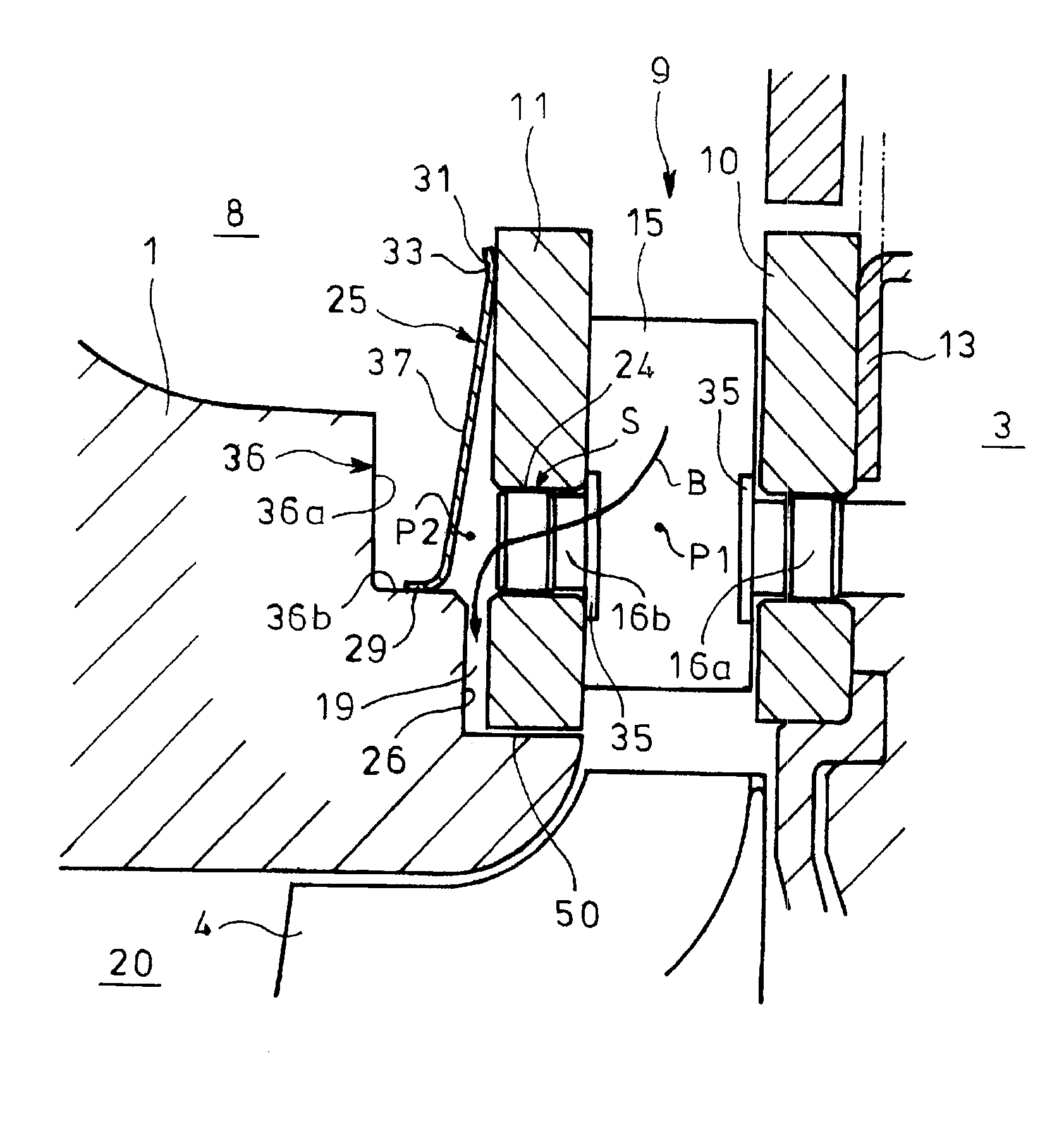
[0038] figure 2 represents an embodiment of the present invention, which will be described in figure 1In the variable capacity turbocharger, the rear exhaust gas introduction wall 11 having the extension part 11' is used as the disc-shaped rear exhaust gas introduction wall 51, whereby the front exhaust gas introduction wall 10 and the rear row The gas introduction walls 51 are each formed in a disc shape. And it is preferable that the disc-shaped rear exhaust gas introduction wall 51 and the disc-shaped front exhaust gas introduction wall 10 are formed of the same material, or are formed of materials having the same coefficient of linear expansion, by which the rear The linear expansion coefficients of the exhaust gas introduction wall 51 and the front exhaust gas introduction wall 10 are equal, so that the vane shafts 16a, 16b fixed on both sides of the nozzle vane...


PUM


Abstract

Disclosed is a variable geometry turbocharger wherein a clearance (19) is provided between a turbine housing (1) and a rear exhaust introduction wall (51) of an exhaust nozzle (9) in which a nozzle vane (15) is sandwiched by a front exhaust introduction wall (10) and the rear exhaust introduction wall (51); and in order to prevent exhaust gas in a scroll passage (8) from leaking to a turbine impeller (4) through the clearance (19), a seal device (25) is disposed upstream of a through-hole (24) through which a vane shaft (16a) passes, in the exhaust gas flow direction, said through-hole being provided in the rear exhaust introduction wall (51). The front exhaust introduction wall (10) and the rear exhaust introduction wall (51) respectively have a disk shape, and a stepped portion (50) in which the disk-shaped rear exhaust introduction wall (51) is fitted along with the clearance (19), is provided in the turbine housing (1).

Description

technical field [0001] The present invention relates to a variable capacity turbocharger capable of improving turbine efficiency with a simple configuration and enabling smooth movement of nozzle vanes. Background technique [0002] figure 1 It is a longitudinal sectional view showing the overall structure of a variable capacity turbocharger to which the present invention is applied. In this turbocharger, the turbine casing 1 and the compressor casing 2 are assembled into one body with fastening bolts 3a, 3b through the bearing casing 3, and the turbine impeller 4 arranged in the turbine casing 1 and the The compressor impeller 5 in the housing 2 is connected by a turbine shaft 7 , and the turbine shaft 7 is rotatably supported by the bearing housing 3 via a bearing 6 . [0003] An exhaust nozzle 9 is provided on the turbine housing side of the bearing housing 3 for guiding the exhaust gas introduced into the scroll channel 8 of the turbine housing 1 to the turbine wheel 4...

Claims


Application Information

Patent Timeline
Patent Type & Authority Applications(China)
IPC IPC(8): F02B37/24F02B39/00
CPCF01D17/14F05D2240/58F01D25/24F01D17/162F05D2220/40Y02T10/144F02B37/24F01D17/165F02B39/00
Inventor 松山良满井上智裕酒井康隆
Owner IHI CORP
Why Eureka
Try Eureka