Installation device for wall hidden pipeline

A pipeline installation and wall technology, applied to vertical pipelines, building components, buildings, etc., can solve the problems of uneconomical, damaged decoration effect, inconvenience, etc., and achieve the effect of convenient operation, economical and practical

Inactive Publication Date: 2012-11-07
胡智慧 +1
View PDF5 Cites 4 Cited by
  • Summary
  • Abstract
  • Description
  • Claims
  • Application Information

AI Technical Summary

Problems solved by technology

However, due to the built-in pipeline, once the water pipe in the wall leaks or the circuit breaks down, it is necessary to smash the decorated wall or floor, and then repair the water pipe or circuit in the wall. The whole process is not only time-consuming and laborious, Destroying the original decoration effect is not economical and inconvenient

Method used


Image

  • Installation device for wall hidden pipeline
  • Installation device for wall hidden pipeline
  • Installation device for wall hidden pipeline

Examples


Embodiment 1

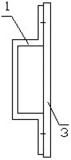
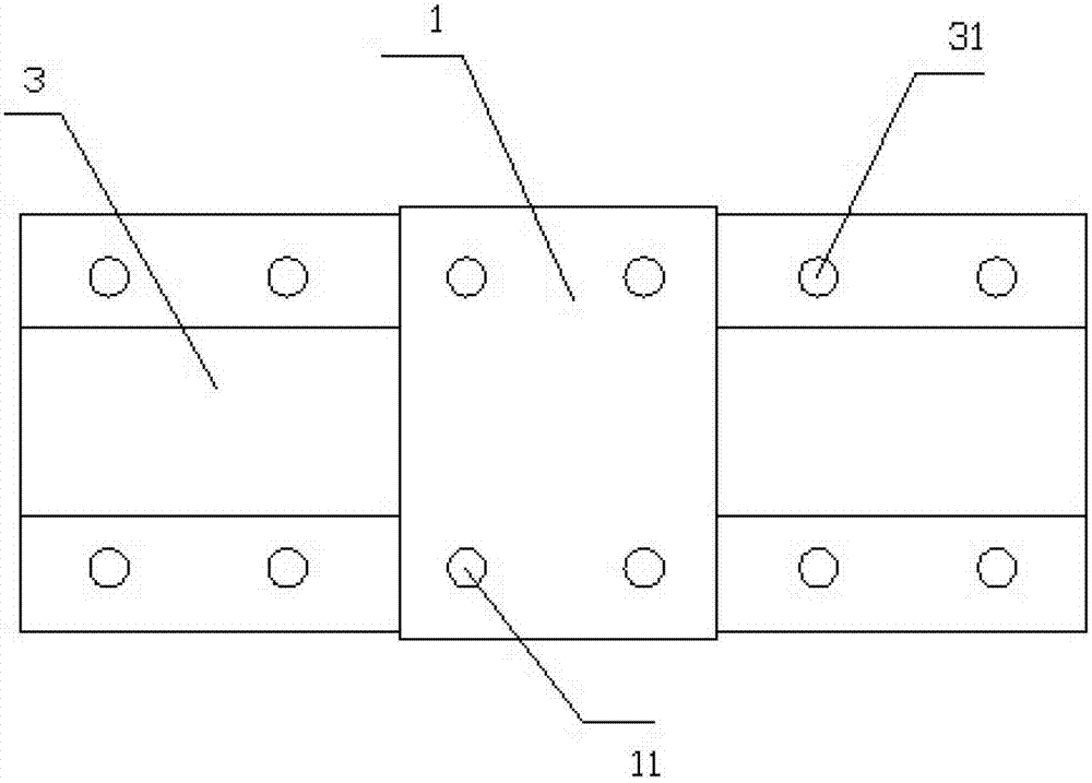
[0023] Such as image 3 , Figure 4 with Figure 5 As shown, there is a fixing hole A31 on the folding plates on both sides of the fixing frame 3, and a fixing hole B11 of the same size is opened on the outer sealing plate 1 corresponding to the fixing hole A31, and the fixing frame 3 passes through the folding plates on both sides. The fixing hole A31 on the top is fixedly connected with the fixing hole B11 of the outer sealing plate 1 .

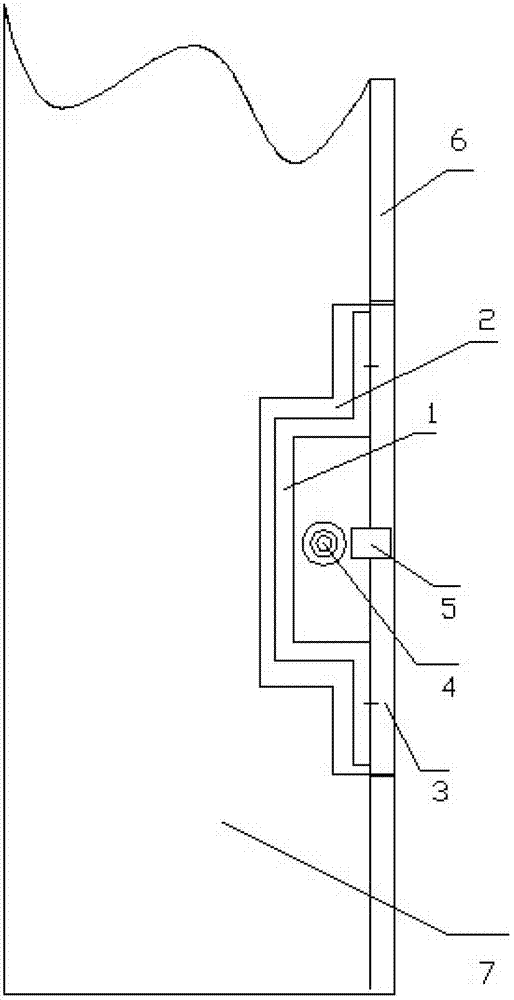
[0024] When in use, first, according to the actual laying needs of the pipeline 4, reserve or excavate the groove 2 on the inner wall body 7 for installing the fixing frame 3 and match it, and then install the fixing frame 3 in the groove 2 , the pipeline 4 is laid in the detour part of the fixing frame 3, and the outer sealing plate 1 and the fixing frame 3 are fixedly connected through the fixing hole B11 on the outer sealing plate 1 and the fixing holes A31 on the folded plates on both sides of the fixing frame 3, and the pipeline 4 c...

Embodiment 2

[0026] Such as Image 6 , Figure 7 with Figure 8 As shown, a locking part 32 is provided on both side flaps of the fixed frame 3, and a locking matching part 12 is provided on the inner side of the outer sealing plate 1 corresponding to the locking part 32. The locking part 32 Including the hinge A321 and the locking groove 322, the locking fitting part 12 includes the hinge B121 and the locking head 122, the hinge A321 is connected with the hinge B121, the locking groove 322 is fastened and connected with the locking head 122, which can facilitate Remove and open.

[0027] When in use, first, according to the actual laying needs of the pipeline 4, reserve or excavate the groove 2 on the inner wall body 7 for installing the fixing frame 3 and match it, and then install the fixing frame 3 in the groove 2 , the pipeline 4 is laid in the detour part of the fixing frame 3, and the outer sealing plate 1 and the fixing frame 3 are fixedly connected through the fixing hole B11 o...


PUM


Abstract

The invention discloses an installation device for a wall hidden pipeline, belonging to the field of an installation device for a pipeline. The installation device comprises a fixed frame and an outer sealing plate which is matched with the fixed frame, wherein a convoluted part is arranged between folding plates on the two sides of the fixed frame; and the fixed frame is connected with the outer sealing plate by the folding plates on the two sides. The installation device has the advantages that: in the using process, a groove which is matched with and is used for installing the fixed frame is presrved or dug in the wall body; the fixed frame is arranged inside the groove for paving the pipeline inside the fixed frame; and the outer sealing plate is used to seal the outer surface of the fixed frame; the pipeline is sealed, so that the outer sealing surface of the outer sealing plate and the outer wall are kept in the same plane. The installation device can directly achieve the pavement of the hidden pipeline; in a maintaining process, the wall and the ground are not needed to be dug, and anti-leakage maintenance for the pipeline can be directly carried out only by opening or taking down the outer sealing plate; and besides, the installation device is economical and practical, and convenient to operate.

Description

technical field [0001] The invention relates to a wall hidden pipeline installation device, which belongs to the field of pipeline installation devices. Background technique [0002] Hidden pipelines in the wall are common items in the wall water pipes, wires and pipelines decoration projects in living rooms, kitchens, toilets and washrooms of residential buildings or public buildings. Because the pipelines are hidden, they are beautiful and tidy, and are currently widely used. However, due to the built-in pipeline, once the water pipe in the wall leaks or the circuit breaks down, it is necessary to smash the decorated wall or floor, and then repair the water pipe or circuit in the wall. The whole process is not only time-consuming and laborious, It is uneconomical and inconvenient to destroy the original decoration effect. Contents of the invention [0003] In view of the problems existing in the above-mentioned prior art, the present invention provides a wall hidden pip...

Claims


Application Information

Patent Timeline
Patent Type & Authority Applications(China)
IPC IPC(8): E04F17/08
Inventor 胡智慧胡俊峰
Owner 胡智慧
Why Eureka
Try Eureka