
Tower pole base mounting device in cold climate

An installation device and climate technology, applied in the direction of towers, building types, buildings, etc., can solve the problems of unsolved problems of tower base installation in cold climates, and achieve the effect of ensuring stability

Pending Publication Date: 2018-11-13
国网河南省电力公司唐河县供电公司
View PDF6 Cites 0 Cited by
  • Summary
  • Abstract
  • Description
  • Claims
  • Application Information

AI Technical Summary

Problems solved by technology

The invention has the advantages of reasonable path, short construction period, low investment and convenient operation and maintenance, which fills the blank of erecting poles and towers under the geological conditions of coal gangue areas, and provides a basis for erecting concrete poles and communication poles under geological conditions such as coal gangue, oil shale, and strong weathered rock in the future. , spanning frame, ring network cabinet, box transformer and even a new substation to provide technical support and lay a solid foundation; it only discloses a method for erecting a tower base, but it does not solve the problem of tower base installation in cold climates

Method used


Image

  • Tower pole base mounting device in cold climate
  • Tower pole base mounting device in cold climate
  • Tower pole base mounting device in cold climate

Examples


Embodiment 1

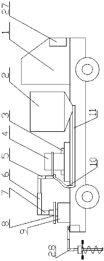
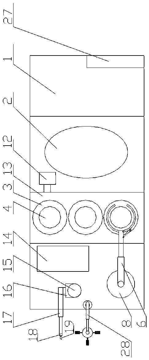
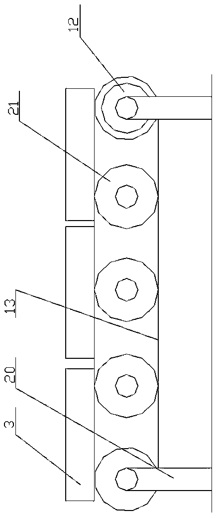
[0027] A tower rod base installation device in cold climates, comprising a foundation pit excavation mechanism 28 arranged on the mobile trolley 1, a bearing mechanism arranged on the mobile trolley 1, arranged on the mobile trolley 1 and connected with the mobile trolley 1 The installation mechanism that matches the bearing mechanism, the pouring mechanism that is arranged on the mobile trolley and cooperates with the installation mechanism, the laying mechanism that is arranged on the said mobile trolley, and the foundation pit that is arranged on the mobile trolley The control mechanism of the excavation mechanism 28, the bearing mechanism, the installation mechanism, the pouring mechanism and the laying mechanism;

[0028] The foundation pit excavation mechanism 28 includes an excavation steering motor 281 arranged on the mobile trolley 1, a foundation pit telescopic arm 282 arranged on the output shaft of the excavation steering motor 281, and a foundation pit telescopic a...

Embodiment 2

[0037] The difference from Embodiment 1 is that the control mechanism 27 is a PLC installed on the moving trolley.

[0038] The installation base column, installation telescopic column, installation telescopic arm, opening and closing telescopic rod, laying telescopic rod, laying column, and laying arm used in this implementation are all hydraulic telescopic rods, and an oil pool is set on the mobile trolley, because it is a conventional The technical means will not be described in detail in this embodiment.

Embodiment 3

[0040] The difference from the second embodiment is that the diameter of the earth drill is 600 mm and the depth is 1000 mm.

[0041] The method of ground drilling can quickly excavate the ground to meet the specified foundation pit.


PUM


Abstract

The invention provides a tower pole base mounting device in cold climate. The tower pole base mounting device comprises a foundation pit excavation mechanism, a bearing mechanism, a mounting mechanism, a pouring mechanism, a laying mechanism and a control mechanism, wherein the foundation pit excavation mechanism is arranged on a moving trolley; the bearing mechanism is arranged on the moving trolley; the mounting mechanism is arranged on the moving trolley and matched with the bearing mechanism; the pouring mechanism is arranged on the moving trolley and matched with the mounting mechanism; the laying mechanism is arranged on the moving trolley; and the control mechanism is arranged on the moving trolley and used for controlling the foundation pit excavation mechanism, the bearing mechanism, the mounting mechanism, the pouring mechanism and the laying mechanism. The phenomenon that multiple constructors conduct on-site construction simultaneously in the cold climate is reduced, foundation pit excavation can be conducted, precast pieces are pre-buried, gaps are poured, and a heat-insulation grass mat is laid after pouring.

Description

technical field [0001] The invention relates to the technical field of tower rod erection equipment, in particular to a tower rod base installation device in cold weather. Background technique [0002] During the construction of power towers, especially in the northern grasslands in winter, due to the cold weather, in order to ensure the normal progress of the construction period, on-site construction operations are required even if the temperature is low. The existing operation methods often require The user excavated the site, put the prefabricated foundation into the excavated foundation pit, and then poured concrete around it to ensure the stability of the structure. However, due to the harsh climate of the grassland in winter, the During on-site construction, not only multi-person coordination is required, but also accurate docking is required, which increases the difficulty of implementation and adds many unstable factors to the normal progress of the construction peri...

Claims


Application Information

Patent Timeline
Patent Type & Authority Applications(China)
IPC IPC(8): E04H12/34E04H12/22
CPCE04H12/2253E04H12/347
Inventor 陈慎秦航
Owner 国网河南省电力公司唐河县供电公司
Learn More