Method for confirming relay node and corresponding candidate relay node

A relay node and node technology, applied in the field of communication, can solve the problem of high computational complexity, achieve the effect of reducing computational complexity and control overhead

Active Publication Date: 2012-11-07
ALCATEL LUCENT SHANGHAI BELL CO LTD
View PDF4 Cites 14 Cited by
  • Summary
  • Abstract
  • Description
  • Claims
  • Application Information

AI Technical Summary

Problems solved by technology

[0007] The disadvantage of this scheme is that when the number of relay clusters is not small, and the number of nodes in each relay cluster is not small, a large amount of control overhead is required, and the computational complexity is high

Method used


Image

  • Method for confirming relay node and corresponding candidate relay node
  • Method for confirming relay node and corresponding candidate relay node
  • Method for confirming relay node and corresponding candidate relay node

Examples


Embodiment Construction

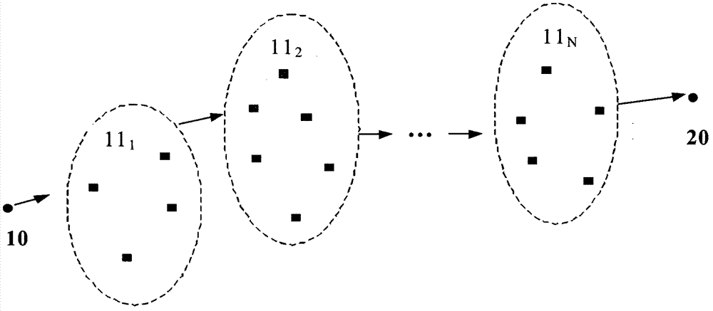
[0021] Embodiments according to the present invention will now be described in detail with reference to the accompanying drawings. Among them, according to the embodiment of the present invention, such as figure 1 Performed in the multi-hop relay network shown.
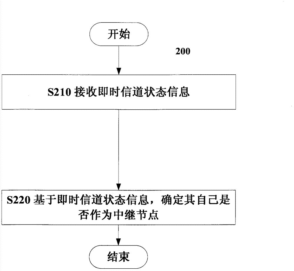
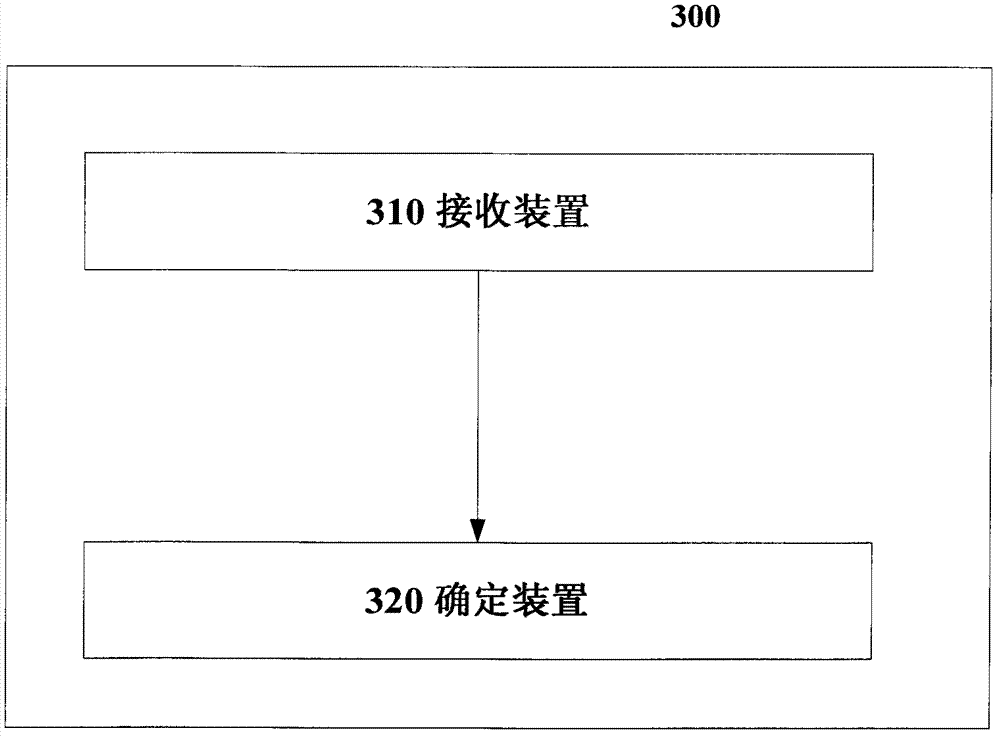
[0022] The central idea of ​​the present invention is that a corresponding candidate relay node in a corresponding relay cluster determines by itself whether it is a relay node of the corresponding relay cluster.

[0023] Compared with the above-mentioned global joint optimization, the present invention does not require a central controller, can reduce control overhead, and reduce computational complexity.

[0024] One main way to select relay nodes is to select a relay node from each relay cluster to form a "single node to single node" route. Another possible way of selecting relay nodes is to select multiple relay nodes from each relay cluster to form a "multi-node to multi-node" route. However, for "multi-node-t...


PUM


Abstract

The invention discloses a method for confirming a relay node in a corresponding relay cluster of a multihop relay network and a corresponding candidate relay node in the corresponding relay cluster of the multihop relay network. The method comprises the following steps: receiving instant channel state information from the corresponding candidate relay node to a node of a next stage of the relay cluster or a target node, which is fed back by the node of the next stage of the relay cluster of the corresponding relay cluster or the target node, by the corresponding candidate relay node in the corresponding relay cluster; and at least based on the received instant channel state information, determining whether to be used as a relay node of the corresponding relay cluster by the corresponding candidate relay node. According to the method, the control overhead and the computation complexity can be reduced.

Description

technical field [0001] The present invention relates to the communication field, and more specifically, the present invention relates to a method for determining a relay node in a corresponding relay cluster in a multi-hop relay network and a corresponding candidate relay node in a corresponding relay cluster in the multi-hop relay network. Background technique [0002] Currently, multi-hop relay networks are attracting more and more attention. figure 1 A multi-hop relay network is schematically shown. like figure 1 As shown, in addition to the source node 10 and the destination node 20, the multi-hop relay network includes a plurality of relay clusters 11 represented by dotted circles 1 、11 2 ,...,11 N . like figure 1 As shown by the black dots in the dotted circles in , each relay cluster can include multiple nodes. In addition, the number of nodes in each relay cluster can be the same or different. Among them, from the source node 10 to the first relay cluster 11 ...

Claims


Application Information

Patent Timeline
Patent Type & Authority Applications(China)
IPC IPC(8): H04W40/10H04W40/22
Inventor 张路
Owner ALCATEL LUCENT SHANGHAI BELL CO LTD
Why Eureka
Try Eureka