Asymmetric stator teeth in an electric motor

An asymmetric, stator technology used in motorized assemblies, synchronous motors with stationary armatures and rotating magnets, electromechanical devices, etc. to address performance requirements, packaging constraints imposed by design constraints, etc.

Active Publication Date: 2012-11-14
GM GLOBAL TECH OPERATIONS LLC
View PDF3 Cites 7 Cited by
  • Summary
  • Abstract
  • Description
  • Claims
  • Application Information

AI Technical Summary

Problems solved by technology

It is known that performance requirements, packaging constraints, and cost impose constraints on motor design affecting design characteristics

Method used


Image

  • Asymmetric stator teeth in an electric motor
  • Asymmetric stator teeth in an electric motor
  • Asymmetric stator teeth in an electric motor

Examples


Embodiment Construction

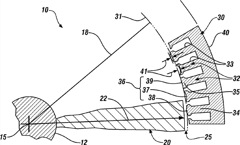
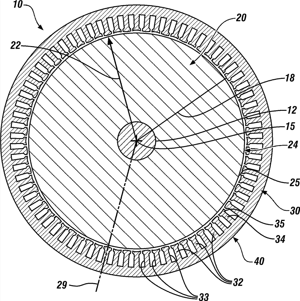
[0014] Referring now to the drawings, which are shown for purposes of illustrating certain exemplary embodiments only and not for purposes of limiting the invention, figure 1 is a cross-sectional view of a permanent magnet electric motor 10 comprising: a rotor 20 mounted on a shaft 12 and inserted into a hollow cylindrical stator 30; figure 2 is a partial sectional view of the permanent magnet electric motor 10 . The permanent magnet electric motor 10 includes a housing with end caps on which a shaft 12 of a rotor 20 is rotatably mounted. The centerline of the shaft 12 defines a longitudinal axis 15 which is the axis of rotation of the rotor 20 and also the longitudinal axis of the stator 30 . The sectional view of the permanent magnet electric motor 10 is shown normal to the longitudinal axis 15 . The salient features of the electric motor are primarily described on the basis of a sectional view perpendicular to the longitudinal axis 15 . A portion of an imaginary circle ...


PUM


Abstract

The present invention relates to asymmetric stator teeth in an electronic motor. A permanent magnet motor includes a permanent magnet rotor, a stator surrounding the rotor having a plurality of teeth radially inwardly oriented toward a longitudinal axis of the stator, wherein each tooth has a tooth length and a tooth tip surface geometry. An asymmetric air gap is defined by variations in the tooth lengths and tooth tip surface geometries.

Description

technical field [0001] The present disclosure relates to stators for electric motors. Background technique [0002] The statements in this section merely provide background information related to the present disclosure. Accordingly, such statements are not intended to constitute an admission of prior art. [0003] Known electric motors include permanent magnet electric motors that convert electrical power into mechanical torque. The permanent magnet electric motor may be a polyphase internal permanent magnet (IPM) electric motor comprising an annular stator into which a rotor element is inserted. A known stator comprises an annular stator core and a plurality of electrical windings. The known stator core comprises a plurality of radially inwardly projecting tooth elements parallel to the longitudinal axis of the electric motor and defining the inner periphery of the stator. Adjacent radially inwardly projecting tooth elements form radially oriented longitudinal slots. T...

Claims


Application Information

Patent Timeline
Patent Type & Authority Applications(China)
IPC IPC(8): H02K1/12H02K1/27
CPCH02K2201/03H02K1/16H02K21/16H02K29/03
Inventor S.朱尔科维奇X.周Q.牛K.M.拉曼J.C.摩根特X.韩E.L.凯泽
Owner GM GLOBAL TECH OPERATIONS LLC
Why Eureka
Try Eureka