
Configurable D latch for chaos computing

A latch and chaotic technology, applied in the direction of electrical components, logic circuits, pulse technology, etc., can solve problems that cannot be rewired or configured, functions cannot be changed, and circuit structure cannot be rewired or configured.

Inactive Publication Date: 2012-11-14
SOUTH CHINA UNIV OF TECH
View PDF5 Cites 2 Cited by
  • Summary
  • Abstract
  • Description
  • Claims
  • Application Information

AI Technical Summary

Problems solved by technology

However, traditional D-Latches are static in nature and cannot be rewired or configured during operation.
For example, once a hardware component such as an 8-bit D-type latch is successfully manufactured, its function cannot be changed because its circuit structure cannot be rewired or configured.

Method used


Image

  • Configurable D latch for chaos computing
  • Configurable D latch for chaos computing
  • Configurable D latch for chaos computing

Examples


Embodiment

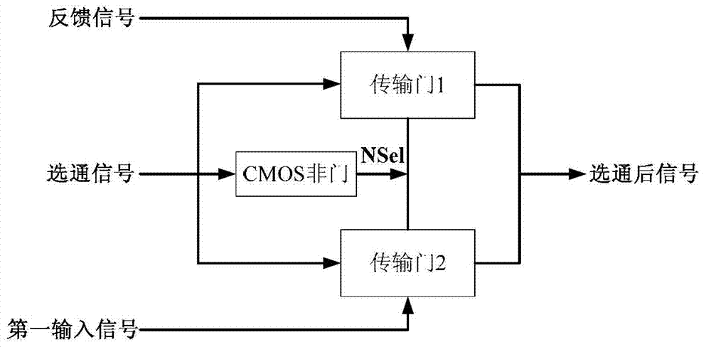
[0024] Such as figure 1 Shown is a configurable D latch used for chaotic computing, including a two-to-one data strobe and a configurable logic gate;

[0025] The two-select-one data strobe: the input signals are the first input signal and the feedback signal, the control signal is the strobe signal, and the output signal is the post-strobe signal;

[0026] The configurable logic gate: the input signals are the gated signal and the second input signal, the control signals are the control signal Ctra, the control signal Ctrb, and the output signals are the output signal Vout and the output signal NVout;

[0027] The output signal Vout is the input signal of the one-of-two data strobe, that is, the feedback signal.

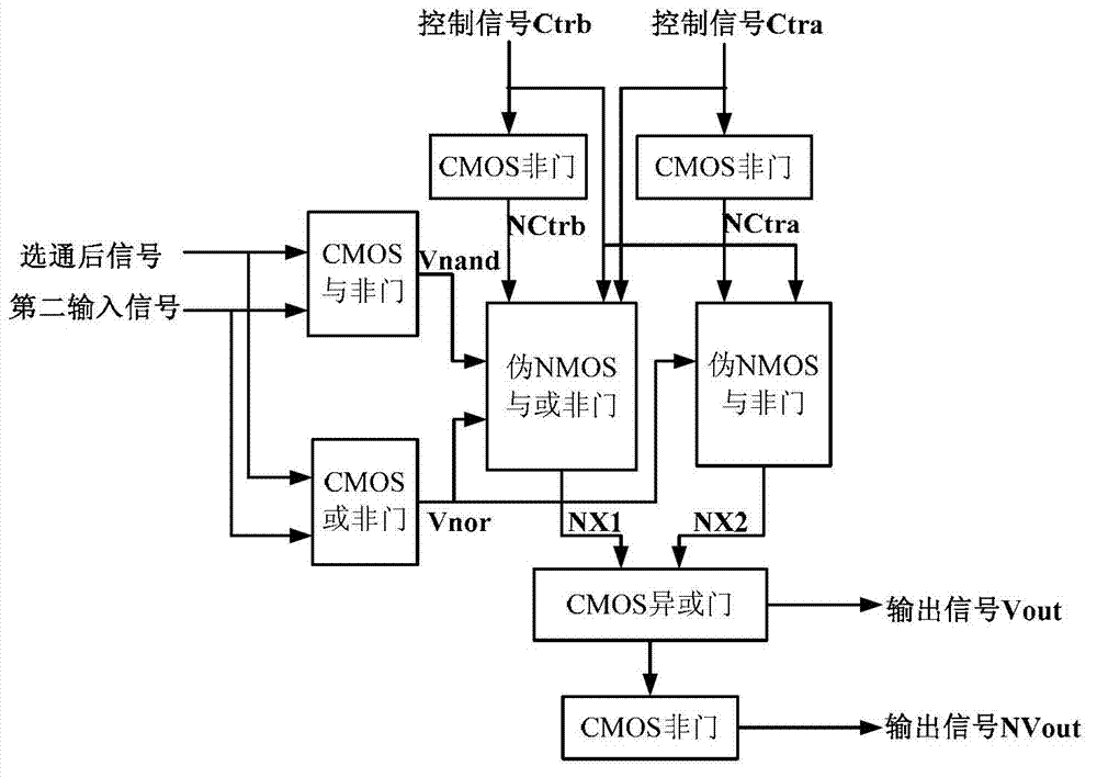
[0028] Such as figure 2 Shown is the structure diagram of configurable logic gate,

[0029] The configurable logic gate includes a CMOS NAND gate, a CMOS NOR gate, three CMOS NOT gates, a CMOS XOR gate, a pseudo NMOS NAND gate, and a pseudo NMOS NAND gate.

[0030] The gated ...


PUM


Abstract

The invention discloses a configurable D latch for chaos computing. The configurable D latch for the chaos computing comprises an alternative data strobe device and a configurable logic gate. According to the alternative data strobe device, input signals are a first input signal and a feedback signal respectively, a control signal is a strobe signal, and an output signal is a signal after strobe. According to the configurable logic gate, input signals are a signal after strobe and a second input signal, control signals are a control signal Ctra and a control signal Ctrb respectively, and output signals are an output signal Vout and an out signal NVout. The output signal Vout of the configurable logic gate is the input signal, namely the feedback signal of the alternative data strobe device. By configuration of the two control signals and the other input signal of the configurable logic gate, the D latch can achieve different functions so as to achieve dynamic computing.

Description

Technical field [0001] The invention relates to the fields of electronic technology and dynamic calculations, and in particular to a configurable D latch for chaotic calculations. Background technique [0002] The latch is a memory cell circuit sensitive to the pulse level. It can change its state under the action of a specific input pulse level. Usually, the pulse level has only two states: high and low. When the pulse level is high and effective, if the input pulse level is high, then the output of the latch will follow the input of the latch and change, if the input pulse level is low, then the output of the latch Will remain the same. On the contrary, when the pulse level is active low, if the input pulse level is low, then the output of the latch will follow the input of the latch and change, if the input pulse level is high, then the latch The output will remain unchanged. [0003] The latch is the main module of the arithmetic unit in the microprocessor, and the D latch ...

Claims


Application Information

Patent Timeline
IPC IPC(8): H03K19/0948
Inventor 姜小波黎红源袁群
Owner SOUTH CHINA UNIV OF TECH
Learn More