Desiccant air conditioning device

An air-conditioning device and air technology, which is applied in air-conditioning systems, air treatment details, space heating and ventilation, etc., and can solve problems such as the deterioration of moisture absorption capacity, the limitation of the ability of dehumidification air-conditioning devices to control humidity or temperature, and the improvement of dryness.

Inactive Publication Date: 2012-11-21
YANMAR CO LTD
View PDF6 Cites 2 Cited by
  • Summary
  • Abstract
  • Description
  • Claims
  • Application Information

AI Technical Summary

Problems solved by technology

[0005] This desiccant air conditioner a is limited in its ability to control humidity or temperature because the dehumidification capacity depends on the performance of the desiccant rotor d
In particular, since the desiccant rotor d generates hygroscopic heat when absorbing moisture into the air SA passing through the introduction pipe b, the moisture absorption capacity deteriorates, and the improvement of the dryness is also limited.

Method used


Image

  • Desiccant air conditioning device
  • Desiccant air conditioning device
  • Desiccant air conditioning device

Examples


Embodiment Construction

[0035] Hereinafter, embodiments of the present invention will be described with reference to the drawings.

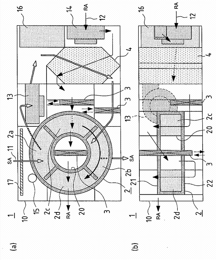
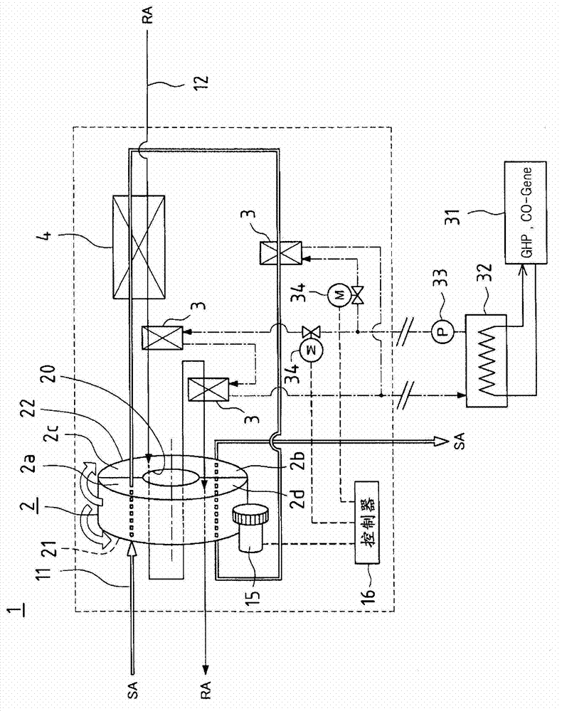
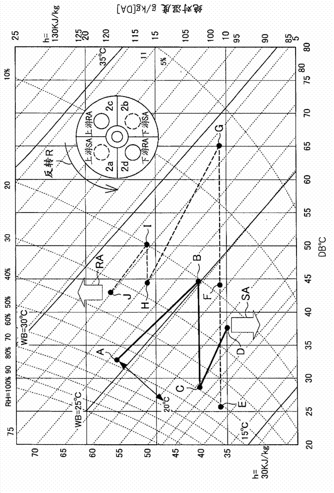
[0036] figure 1 Schematically shows the overall structure of the desiccant air-conditioning device 1 according to the present invention, figure 2 shows a refrigerant circuit diagram of the desiccant air-conditioning device 1, and image 3 A psychrometric diagram is shown when the desiccant air conditioner is operating in cooling mode.

[0037] Specifically, the desiccant air conditioner 1 includes: an introduction line 11, which allows the air SA from the outside to be introduced into the room; a discharge line 12, which allows the air RA in the room to be discharged to the outside; Dehumidification is performed by the moisture of the air SA introduced into the duct 11, and the dehumidification capacity is regenerated by discharging the moisture to the air RA flowing through the exhaust duct 12; the heat exchanger 3 for heating, which is used to heat the exhaust duc...


PUM


Abstract

Provided is a desiccant air conditioning device which has a simple structure and makes it possible for the dehumidifying capability of a desiccant rotor to be effectively exhibited. A desiccant air conditioning device (1) comprises: an inlet passage (11) which introduces air (SA) from an outdoor area to an indoor area; an outlet passage (12) which discharges air (RA) from the indoor area to the outdoor area; a desiccant rotor (2) which dehumidifies the air (SA) flowing through the inlet passage (11) by absorbing moisture from the air (SA), and also restores dehumidifying capability by releasing moisture into the air (RA) flowing through the outlet passage (12); a heating heat exchanger (3) which heats the air (RA) of the outlet passage (12); a sensible heat exchanger (4) which performs heat exchange between the air (SA) flowing through the inlet passage (11) and the air (RA) flowing through the outlet passage (12). A first humidity control region (2a), a second humidity control region (2b), a first restoration region (2c), and a second restoration region (2d) are alternately formed in the desiccant rotor (2). The air (SA) of the inlet passage (11) flows through the first and second humidity control regions (2a, 2b), and the air (RA) of the outlet passage (12) flows through the first and second restoration regions (2c, 2d).

Description

technical field [0001] The present invention relates to a dehumidification air conditioning device using dehumidification or humidification and sensible heat exchange. Background technique [0002] Because the dehumidification air conditioner is different from the refrigeration dehumidification method, it first dehumidifies the air and then cools the air, so there will be no mold or bacteria breeding, and the dehumidification air conditioner does not need to use Freon. Therefore, the dehumidification air conditioner is used as the future air conditioner. attention. [0003] Figure 9 The structure of a typical desiccant air conditioner a is shown. That is, the desiccant air conditioner a is constructed by arranging the introduction duct b allowing the air SA from the outside to flow into the room and the discharge duct c allowing the air RA from the room to flow to the outside in an adjacent convective state so that the air SA and RA flow in the opposite direction, and the...

Claims


Application Information

Patent Timeline
Patent Type & Authority Applications(China)
IPC IPC(8): F24F3/147F24F7/08
CPCF24F2203/1072F24F12/006Y02B30/563F24F3/1423Y02B30/56
Inventor 福留二朗
Owner YANMAR CO LTD
Why Eureka
Try Eureka