Desiccant air conditioner

a desiccant rotor and air conditioner technology, applied in the field of desiccant rotors, can solve the problems of limitation in increasing dryness and deterioration of the ability of moisture absorption, and achieve the effect of efficient showing the ability of desiccant rotors

Inactive Publication Date: 2013-02-14
YANMAR CO LTD
View PDF6 Cites 4 Cited by
  • Summary
  • Abstract
  • Description
  • Claims
  • Application Information

AI Technical Summary

Benefits of technology

[0021]As described above, according to the present invention, it is possible to efficiently show ability of a desiccant rotor.

Problems solved by technology

The desiccant air conditioner a has a limitation in the ability of controlling the humidity or temperature, because the dehumidifying ability depends on the performance of the desiccant rotor d. In particular, since the desiccant rotor d generates moisture absorption heat when absorbing moisture from the air SA passing through the introduction line b, the moisture absorption ability is deteriorated, so there is a limitation in increasing dryness.

Method used


Image

  • Desiccant air conditioner
  • Desiccant air conditioner
  • Desiccant air conditioner

Examples


Embodiment Construction

[0031]Hereinafter, embodiments of the present invention will be described with reference to the accompanying drawings.

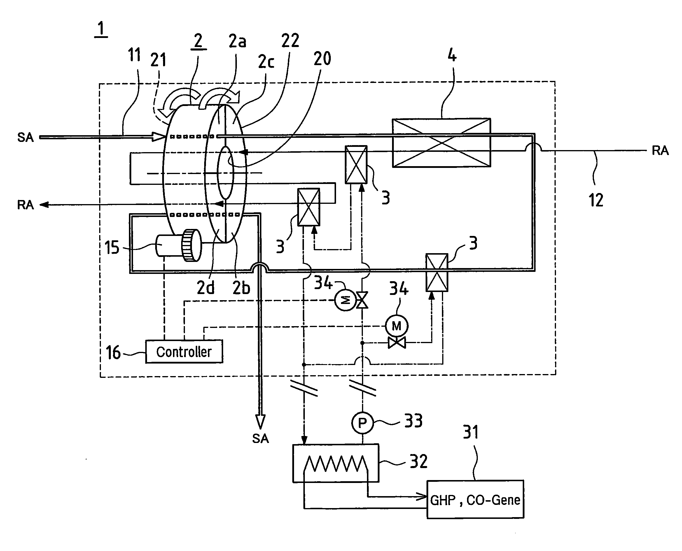
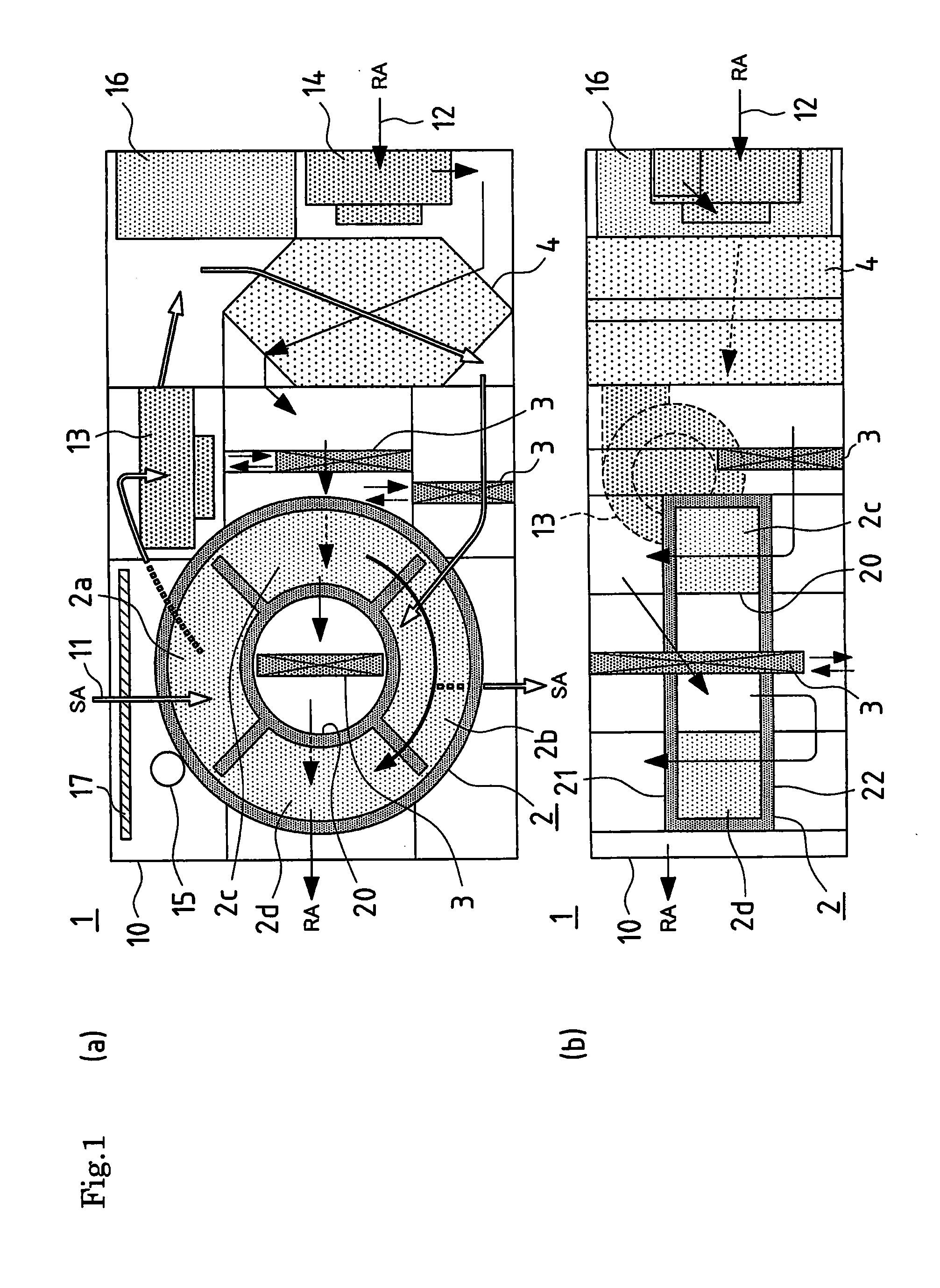
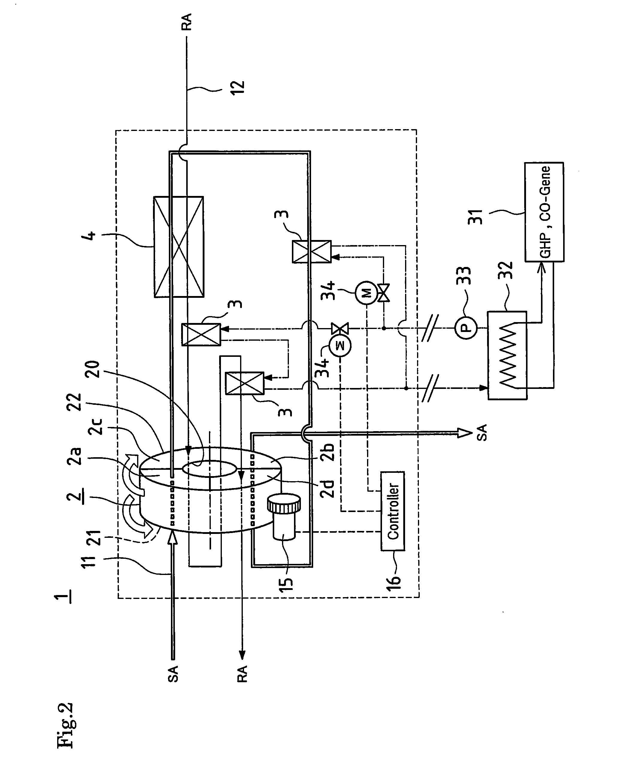
[0032]FIG. 1 schematically shows the entire configuration of a desiccant air conditioner 1 according to the present invention, FIG. 2 shows a refrigerant circuit diagram of the desiccant air conditioner 1, and FIG. 3 shows a psychrometric diagram when the desiccant air conditioner operates in a cooling mode.

[0033]In detail, the desiccant air conditioner 1 includes an introduction line 11 allowing air SA to be introduced into a room from an outside, a discharge line 12 allowing air RA in the room to be discharged to the outside, a desiccant rotor 2 performing dehumidification by absorbing moisture from the air SA flowing through the introduction line 11 and regenerating dehumidifying ability by discharging moisture to the air RA flowing through the discharge line 12, a heating heat exchanger 3 for heating the air RA in the discharge line 12, and a sensible heat exchan...


PUM


Abstract

Provided is an air conditioning system capable of high efficiency operation and a compact structure. The air conditioning system is provided with a desiccant and a heat pump. The desiccant absorbs air moisture and the heat pump employs the treating air as a low-temperature heat source while employing the reproducing air as a high-temperature heat source to supply reproducing air with heat for reproducing the desiccant. Heat exchange occurs between the reproducing air before being heated by the heat pump.

Description

TECHNICAL FIELD[0001]The present invention relates to a desiccant air conditioner using dehumidification or humidification and sensible heat exchange.BACKGROUND ART[0002]Since a desiccant air conditioner, unlike a cooling dehumidification type, cools air after dehumidifying the air, mold or bacteria cannot propagate, and the desiccant air conditioner may not use Freon, so the desiccant air conditioner is spotlighted as the future air conditioner.[0003]FIG. 9 shows the configuration of a common desiccant air conditioner a. That is, the desiccant air conditioner is configured by disposing an introduction line b allowing air SA to flow into a room from the outside and a discharge line c allowing air RA to flow to the outside from the room in an adjacent countercurrent state such that the air SA and RA flows in opposite directions, and by disposing a desiccant rotor d and a sensible heat rotor e across the introduction line b and the discharge line c. Further, the air SA flowing into th...

Claims


Application Information

Patent Timeline
Patent Type & Authority Applications(United States)
IPC IPC(8): B01D53/28
CPCF24F3/1423Y02B30/563F24F2203/1072F24F12/006Y02B30/56
Inventor FUKUDOME, JIRO
Owner YANMAR CO LTD
Why Eureka
Try Eureka