
Artificial lung

A technology of artificial lung and diaphragm, applied in the field of artificial lung

Inactive Publication Date: 2012-11-28
MSA AUER GMBH
View PDF3 Cites 8 Cited by
  • Summary
  • Abstract
  • Description
  • Claims
  • Application Information

AI Technical Summary

Problems solved by technology

[0006] The disadvantage of an artificial lung in which all three lung chambers form a closed system with their respective enclosed lung chambers is, on the one hand, the large installation space for the lung chambers and, on the other hand, the chamber variations and extruded or inhaled volume flows. linear relationship between

Method used


Image

  • Artificial lung
  • Artificial lung
  • Artificial lung

Examples


Embodiment Construction

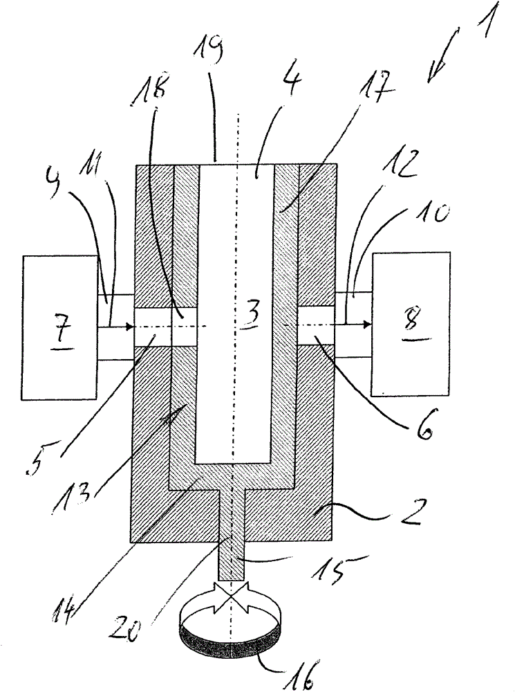
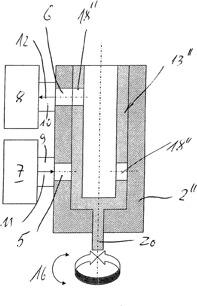
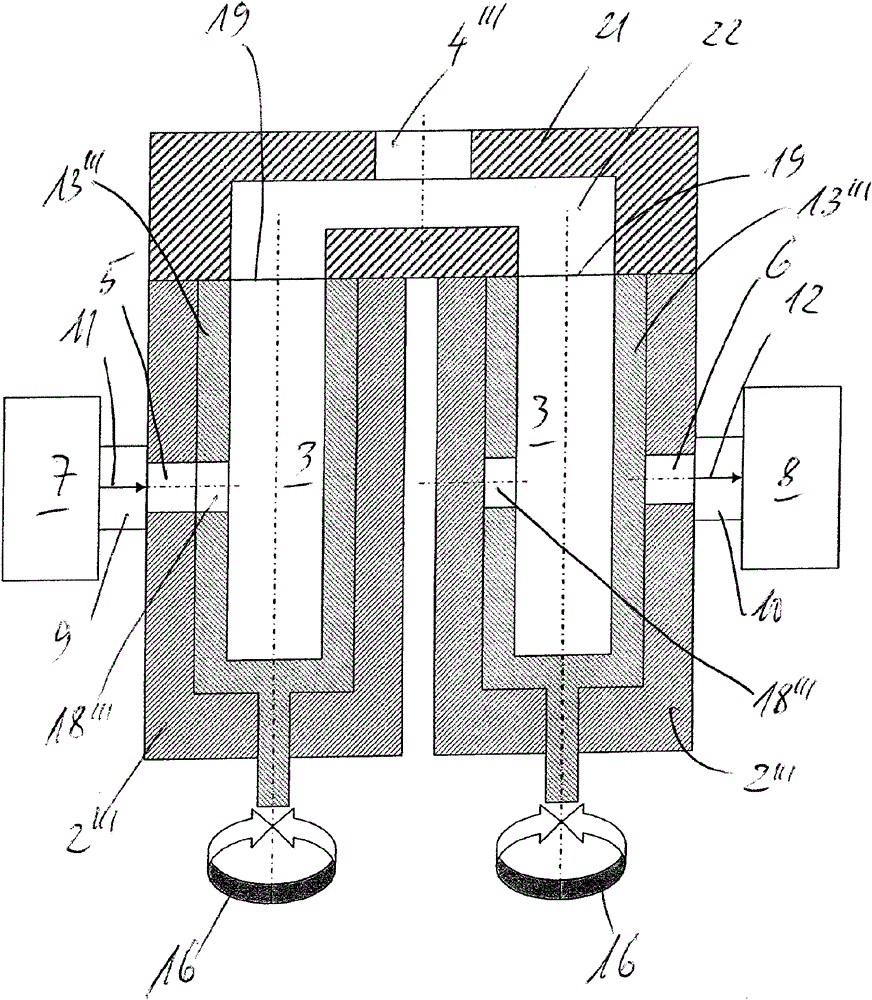
[0034] exist figure 1 The first embodiment of the artificial lung 1 , shown in axial longitudinal section, is used to simulate user loads when testing respiratory protective equipment, in particular compressed-air respiratory protective equipment. For the purpose of the test, the manufacturer establishes a rated value based on the compressed-air respirator to be tested, which must be followed in order to pass the test, especially for compressed-air respirators with automatic lung systems.

[0035] The artificial lung 1 comprises a tubular housing 2 which encloses a lung chamber 3 for breathing air. On the upper side 19, the tubular housing 2 comprises a connection 4 for supplying the breathing air present in the lung chamber 3 to a not shown breathing connection, in particular also not shown, of the respiratory protective device to be tested. Breathing interface of the lung robot. The housing 2 is additionally provided with an inlet 5 and an outlet 6 for breathing air. The ...


PUM


Abstract

The invention relates to an artificial lung for simulating the stress by a user when testing a breathing apparatus, particularly a compressed air breathing apparatus, comprising a housing, which surrounds a pulmonary space for the breathing air and has a connection for supplying the breathing air to the breathing apparatus. In order to be able to variably control the volume flow for generating a certain respiration curve, the housing (2) surrounding the pulmonary space for the breathing air is provided with an inlet (5) and with an outlet (6) for the breathing air, a fan (7, 8) is connected to the inlet and outlet (5, 6), respectively, for supplying and removing the breathing air, and a cover (13), which can be actuated by way of a drive (16) and encloses the pulmonary space (3), is disposed in the housing (2), which cover controls the volume flow of the breathing air between the inlet (5) for the breathing air and the connection (4) for the supply of the breathing air to the breathing apparatus, and / or between the connection (4) and the outlet (6) for removing the breathing air, so as to generate the breathing curve.

Description

technical field [0001] The invention relates to an artificial lung for simulating user loads when testing respiratory protective equipment, in particular compressed air respiratory protective equipment, consisting of a housing surrounding a lung chamber for breathing air, the housing having a Connection for feeding breathing air to the breathing interface of the respiratory protective device. Background technique [0002] Piston lungs, balloon lungs and membrane lungs are previously known as artificial lungs. [0003] Piston lungs consist of a housing surrounding the lung chamber, which has a piston and a connection for supplying breathing air to the breathing connection of the respiratory protective device. The piston lung squeezes air out or sucks in air by changing the volume of the lung chambers. The relationship between the chamber change and the extruded or drawn-in air volume is linear (“Pressureguard” from Infotec AG). [0004] Air-sac lungs are the closest to hum...

Claims


Application Information

Patent Timeline
IPC IPC(8): A62B27/00G09B23/28
CPCG09B23/288G09B23/30A62B27/00
Inventor 弗洛里安·卢克斯彼得·卡多
Owner MSA AUER GMBH
Learn More