Power lead testing system and electronic tag

A detection system, power line technology, applied in the direction of circuit, connection, measurement of electricity, etc., can solve the problems of unresolved manual detection, manual detection, etc.

Inactive Publication Date: 2012-11-28
斯蒂芬・艾伦・莫顿
View PDF9 Cites 2 Cited by
  • Summary
  • Abstract
  • Description
  • Claims
  • Application Information

AI Technical Summary

Problems solved by technology

[0004] Although the plug solves the problem of continued illegal use of wires beyond the specified detection time, the plug still requires manual detection and time-consuming reset of the countdown timer
Document US 2005023118 provides a similar power switch control device, but does not solve the problem of manual detection

Method used


Image

  • Power lead testing system and electronic tag
  • Power lead testing system and electronic tag
  • Power lead testing system and electronic tag

Examples


Embodiment Construction

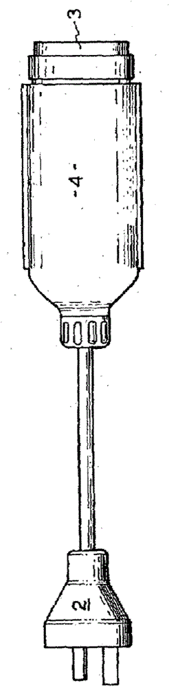
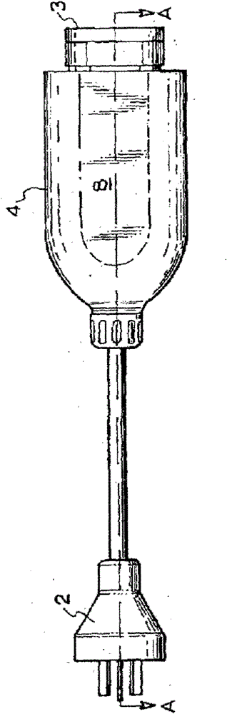
[0042] Figure 2 to Figure 5 A power cord 1 with a three-prong plug 2 and a socket 3 fitted with electrical connectors 4 is shown. Electronic header 4 contains Figure 7 The circuit shown in contains a power supply to convert mains power to 24 volt and 5 volt supplies, a microcontroller with battery backup for real-time countdown and communication with the detection device, a An infrared transceiver circuit and a relay for disconnecting mains power when a specified time has elapsed.

[0043] Sectional view Figure 4 A circuit board 6 is exposed which carries the circuitry described above and also contains LEDs 7 which indicate the condition of the wires 1 . A green LED indicates a safe wire, a flashing LED indicates that the wire will be disconnected within a specified period of time and requires retesting, and a red LED indicates that the wire cannot be used until retested. The transparent top 8 on the connector 4 enables the indicator LED 7 to be seen and also enables th...


PUM


Abstract

A power lead testing system comprises a test unit for applying standard voltage and continuity tests to the lead and an electronic tag integrated with the lead having a countdown timer, said tag communicating with said test unit which resets the timer for a defined period when the lead passes the applied voltage and continuity tests and also incorporates a circuit breaker which is triggered when the lead fails either the voltage or continuity test or when the countdown time elapses, thus isolating the lead.

Description

technical field [0001] The present invention relates to devices for testing compliance with safety standards of power cords and power tools, and to electronic tags for use with the testing devices. Background technique [0002] Electrical safety standards require regular testing and certification of tool power cords and extension cords. At present, the above-mentioned testing and certification is a manual process as follows: the plug of the wire is tested with a testing instrument, and if the specified insulation test and continuity test are met, the wire is marked with a printed label marked with the testing date. [0003] This manual process is time consuming and does not prevent the tool or lead from being used beyond the time required for the next inspection. A solution to the latter problem can be found in document GB 2450466 which discloses an electrical plug fitted with a countdown timer. When the plug is inserted into a live electrical outlet, a countdown timer sta...

Claims


Application Information

Patent Timeline
Patent Type & Authority Applications(China)
IPC IPC(8): G01R31/02G01R31/08G01R31/18
CPCH01R13/6658H01R13/6666G01R31/02G01R31/54
Inventor 斯蒂芬·艾伦·莫顿
Owner 斯蒂芬・艾伦・莫顿
Why Eureka
Try Eureka