Light emitting apparatus

The technology of a light emitting device and a light emitting unit, which is applied in the field of light emitting diode (LED) light emitting devices, can solve the problems of non-operation, burning of light emitting devices or electronic ballasts, etc.

Inactive Publication Date: 2012-12-12
GIO OPTOELECTRONICS CORP
View PDF5 Cites 4 Cited by
  • Summary
  • Abstract
  • Description
  • Claims
  • Application Information

AI Technical Summary

Problems solved by technology

[0008] In addition, if the lamp tube 11 connected with an electronic ballast is replaced by an LED lamp tube of the same shape, the electronic ballast will detect whether the filament exists, but since the LED lamp tube does not have a filament, it is necessary to Remove the electronic ballast of the original lamp and change the circuit, otherwise, the luminous device or electronic ballast may be burned or inoperative

Method used


Image

  • Light emitting apparatus
  • Light emitting apparatus
  • Light emitting apparatus

Examples


Embodiment Construction

[0076] A light emitting device according to a preferred embodiment of the present invention will be described below with reference to related drawings, wherein the same elements will be described with the same reference numerals.

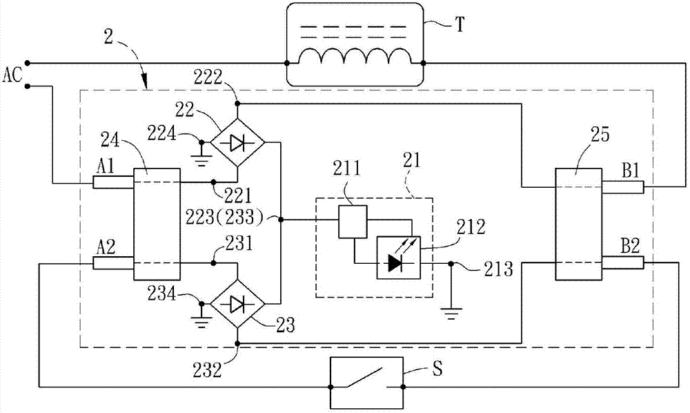
[0077] Please refer to Figure 2A As shown, it is a schematic circuit diagram of a light emitting device 2 according to a preferred embodiment of the present invention. Firstly, the lighting device 2 of the present invention is compatible with known fluorescent tubes with traditional ballasts or electronic ballasts, and can be used to replace known fluorescent tubes. In addition, in order to replace the known fluorescent tube, the appearance of the light emitting device 2 is made to be the same as that of the known fluorescent tube, and can be engaged with the lamp socket of the known lamp. In addition, in order to illustrate the operating principle of the light emitting device 2, Figure 2A The schematic circuit diagram of shows a conventional ba...


PUM


Abstract

A light emitting apparatus receives an external power and includes a light-emitting unit, two rectifiers, a first electrical connection element and a second electrical connection element. Each of the rectifiers has a first input terminal, a second input terminal, an output terminal and a ground terminal. The output terminals are electrically connected together and are electrically connected with the light-emitting unit. The first electrical connection element is electrically connected with the external power and the first input terminals. The second electrical connection element is electrically connected with the external power and the second input terminals. The light emitting apparatus can replace the traditional fluorescent tube without changing the circuit of the lighting.

Description

technical field [0001] The present invention relates to a light emitting device, in particular to a light emitting diode (LED) light emitting device. Background technique [0002] Please refer to Figure 1A and Figure 1B As shown, they are respectively a schematic diagram and a schematic circuit diagram of a known fluorescent lamp 1 . Among them, the fluorescent lamp 1 is an appliance that can convert electrical energy into light energy. [0003] The fluorescent lamp 1 includes a lamp tube 11 and a lamp 12, the lamp tube 11 includes two electrical connection components 111 and a tube body 112, and the lamp 12 includes two lamp holders 121, a ballast 122, a starter 123 and a body 124 ( Figure 1A The stabilizer 122 and the starter 123 are not shown, Figure 1B The lamp holder 121 and the body 124 are not shown). Among them, the lamp holder 121 is arranged on both sides of the main body 124, the ballast 122 and the starter 123 are arranged in the main body 124, and the tw...

Claims


Application Information

Patent Timeline
Patent Type & Authority Applications(China)
IPC IPC(8): F21S2/00F21V23/00H05B37/02F21Y101/02H05B44/00
CPCF21S2/00H05B33/08H05B33/0884F21V23/00H05B37/02F21V23/003Y02B20/383F21K9/17Y02B20/386H05B33/0803H05B33/0809F21K9/278Y02B20/30H05B45/3578H05B45/40H05B47/26F21K9/27
Inventor 林崇智杨武璋
Owner GIO OPTOELECTRONICS CORP
Why Eureka
Try Eureka