
Calibration method of three-dimensional electronic compass

A technology of electronic compass and calibration method, which is applied in directions such as compass, instrument, surveying and mapping and navigation, etc., can solve the problem of inaccurate calibration method and so on.

Active Publication Date: 2012-12-12
HEFEI INSTITUTES OF PHYSICAL SCIENCE - CHINESE ACAD OF SCI
View PDF4 Cites 32 Cited by
  • Summary
  • Abstract
  • Description
  • Claims
  • Application Information

AI Technical Summary

Problems solved by technology

[0007] The purpose of the present invention is to address the inaccurate shortcomings of the existing linear calibration method for calibrating the three-dimensional electronic compass, and propose a method for calibrating the three-dimensional electronic compass using the geomagnetic field. The output value changes of the built-in magnetic sensor and inclination sensor of the compass in different spatial directions are used to calibrate the three-dimensional electronic compass

Method used


Image

  • Calibration method of three-dimensional electronic compass
  • Calibration method of three-dimensional electronic compass
  • Calibration method of three-dimensional electronic compass

Examples


Embodiment Construction

[0065] Below in conjunction with accompanying drawing and embodiment the present invention is described in further detail:

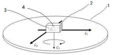
[0066] figure 1 Place a schematic diagram for the 3D electronic compass 2.

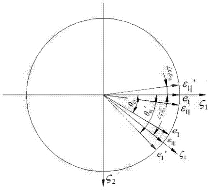
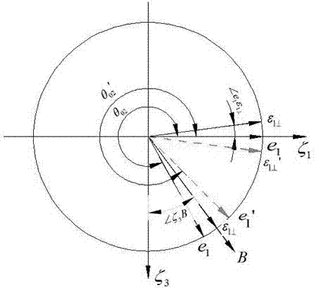
[0067] The placed platform is a three-dimensional non-magnetic rotating platform 1, and its coordinate system is in The axis is downward along the direction of gravity, and the three-dimensional non-magnetic rotating platform 1 can rotate around axis, axis and The shafts are rotated precisely 360°, and the rotation angle can be accurately output by photoelectric encoders and other devices. The surface can be adjusted to be horizontal, and the counterclockwise direction is defined as the positive direction. Three-dimensional electronic compass 2 (the shell coordinate system is e:(e 1 e 2 e 3 )) There are three built-in magnetic sensors 3 (the coordinate system is ε:(ε 1 ε 2 ε 3 )) and an inclination sensor 4 whose coordinate system is ξ:(ξ 1 ξ 2 ξ 3 ))...


PUM


Abstract

The invention discloses a calibration method of a three-dimensional electronic compass. A realizing device of the method comprises a three-dimensional non-magnetic rotating platform and a three-dimensional electronic compass internally provided with a three-dimensional magnetic sensor and an obliquity sensor. Through output changes of the three-dimensional non-magnetic sensor and the obliquity sensor, caused by a geomagnetic field and a gravitational field when the three-dimensional electronic compass rotates spatially, a spatial position relationship among a sensitive direction vector of the sensor, a coordinate system of a shell of the three-dimensional electronic compass and a geodetic coordinate system is determined, and output characteristics of the magnetic sensor and the obliquity sensor are determined to obtain a one-to-one corresponding relationship between an output value and spatial position of the three-dimensional electronic compass, so that standard calibration of the three-dimensional electronic compass is realized. With the adoption of the calibration method provided by the invention, a magnetic shielding room and a Helmholtz coil used in existing calibration method of the magnetic sensor are not needed, the positions of the magnetic sensor and the obliquity sensor inside the three-dimensional electronic compass need not to be adjusted, and high-precision calibration of the three-dimensional electronic compass is realized under the condition that the precise three-dimensional non-magnetic rotating platform exists.

Description

technical field [0001] The invention relates to the calibration of a three-dimensional electronic compass, in particular to a positioning device with a built-in magnetic sensor using the earth's magnetic field. Background technique [0002] The three-dimensional electronic compass uses the built-in magnetic sensor to determine the heading by sensing the earth's magnetic field. The three-dimensional electronic compass also has a built-in inclination sensor. Through inclination compensation, the three-dimensional electronic compass can still accurately determine the direction when it is tilted. The three-dimensional electronic compass is small in size, accurate in indicating direction, and outputs electrical signals. It can be integrated into other electronic systems through various interfaces and is easy to use. It has been widely used in sea, land and air navigation, inertial navigation, autonomous robots, and geological surveys. [0003] Since the three axes of the magnetic...

Claims


Application Information

Patent Timeline
IPC IPC(8): G01C17/38
Inventor 陈池来刘建强程珍
Owner HEFEI INSTITUTES OF PHYSICAL SCIENCE - CHINESE ACAD OF SCI
Learn More