Explosion-field shock wave overpressure filter

A shock wave and filter technology, which is applied in the field of explosive effect testing, can solve the problems of measurement error, narrow frequency response range, curve attenuation, etc., and achieve the effect of increasing transmission distance, saving installation space and shortening length.

Inactive Publication Date: 2012-12-12
XIAN MODERN CHEM RES INST
View PDF5 Cites 19 Cited by
  • Summary
  • Abstract
  • Description
  • Claims
  • Application Information

AI Technical Summary

Problems solved by technology

The existing high-frequency response pressure sensor can accurately obtain the steep shock wave overpressure curve in the initial process of the shock wave pressure-time curve, but due to the small time constant of the high-frequency response sensor, a part of the quasi-steady-state pressure curve after the shock wave cannot be maintained , the curve will quickly attenuate, which will bring large errors to the measurement, and the quasi-steady-state pressure is generally relatively small. Under the condition of satisfying the peak value of the high-range shock wave, measuring a low pressure that is less than dozens of times the range will produce a relatively large measurement error
As for pressure sensors with zero-frequency response, piezoresistive pressure sensors are mainly on the market, and their frequency response range is narrow, which generally cannot meet the shock wave overpressure measurement with a steep rising front at the initial stage of the shock wave, but can satisfy the quasi-static pressure sensor in the latter stage. Pressure measurement requirements, but because the quasi-steady-state pressure is usually very small, the range of the selected piezoresistive pressure sensor is also small, and the peak value of the overpressure at the initial stage of the shock wave is high, and the piezoresistive pressure sensor will be damaged by the steep shock wave ; If a large range sensor is selected, a large measurement error will occur

Method used


Image

  • Explosion-field shock wave overpressure filter
  • Explosion-field shock wave overpressure filter
  • Explosion-field shock wave overpressure filter

Examples


Embodiment Construction

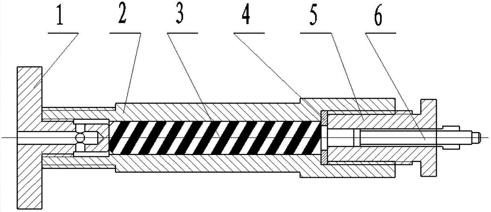
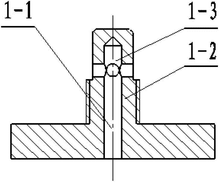
[0021] like figure 1 As shown, this embodiment provides an explosion field shock wave overpressure filter, which is composed of a cover plate 1, a lumen 2, a screw rod 3, a buffer pad 4, a sensor mounting seat 5, and a piezoresistive pressure sensor 6. in:

[0022] The lumen 2 is a cylinder with two central stepped holes. The end of one end of the small stepped hole is provided with an internal thread for matching with the external thread on the cover plate 1. The outer diameter of the small stepped hole is close to the end position An external thread is provided; the inner hole at one end of the large step hole is provided with an internal thread near the end, which is used to cooperate with the external thread on the sensor mounting seat 5, and the outer diameter of the large step hole is hexagonal near the end;

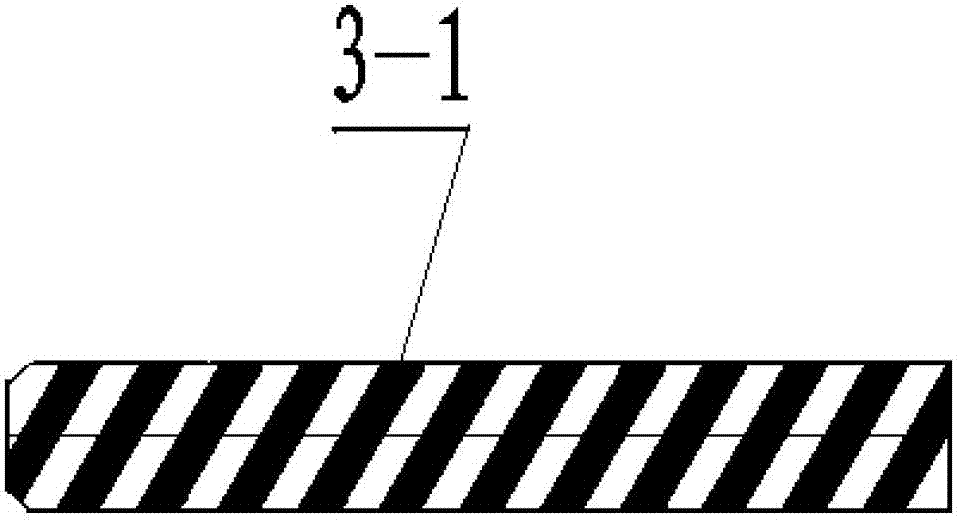
[0023] The screw rod 3 is a cylinder, which is assembled into the inner hole of the small step of the lumen 2;

[0024] The buffer pad 4 is positioned on the ste...


PUM

PropertyMeasurementUnit
widthaaaaaaaaaa
depthaaaaaaaaaa

Abstract

The invention discloses an explosion-field shock wave overpressure filter, which is composed of a cover plate, a tube cavity, a screw rod, a buffer gasket, a sensor installing base and a pressure sensor, wherein one end of the tube cavity is connected with the cover plate, and the other end of the tube cavity is connected with the sensor installing base; the piezoresistive pressure sensor is installed in the sensor installing base; and the inner part of the tube cavity is provided with the screw rod. Explosive is exploded in a closed environment, and shock waves enter from a blind hole in the cover plate, penetrate through cross through holes, and enter into a groove of the screw rod in the tube cavity from gaps around a boss. The shock waves are transmitted along with the screw groove to be weakened, and finally the shock waves are transmitted to the sensitive surface of the pressure sensor. The pressure sensor is subjected to a pressure action and then outputs pressure signals, the pressure signals are amplified through a front adapter, and then a quasi static pressure curve is obtained.

Description

technical field [0001] The invention belongs to the technical field of explosive explosion action testing, and specifically relates to a mechanical filter, in particular to a mechanical filter suitable for real-time filtering of transient shock wave overpressure peaks in an explosion field. Background technique [0002] The temperature-pressure / cloud explosion ammunition explodes in a closed environment, and the shock wave pressure-time curve produced is composed of two parts. The initial part is the process of a sharp rise in pressure, forming a steep shock wave overpressure peak, and then the pressure curve decays and then slowly A quasi-static process that rises and stabilizes to a certain lower pressure value. To obtain this complete pressure-time curve, a pressure sensor that responds to both high-frequency and zero-frequency is required, and it meets the requirement that the measurement error in the high-range and low-range ranges is very small. There is no pressure s...

Claims


Application Information

Patent Timeline
Patent Type & Authority Applications(China)
IPC IPC(8): G01L5/00
Inventor 苏健军李芝绒王胜强殷俊兰姬建荣潘文孔霖苟兵旺张俊峰赵超越
Owner XIAN MODERN CHEM RES INST
Why Eureka
Try Eureka