Impact tool

A technology of impact tools and anvils, which is applied in the field of impact tools, can solve problems such as enlarged impact mechanism parts, hinder miniaturization, and increase costs, and achieve the effects of maintaining miniaturization, good operability, and a small number of parts

Active Publication Date: 2012-12-19
MAKITA CORP
View PDF5 Cites 7 Cited by
  • Summary
  • Abstract
  • Description
  • Claims
  • Application Information

AI Technical Summary

Problems solved by technology

[0006] However, in the mode switching mechanism disclosed in Patent Document 1, since the connection sleeve is fitted on the outer periphery of the hammer, the impact mechanism portion becomes larger in the radial direction, which hinders miniaturization.
In addition, not only the connection sleeve is added, but also a flange needs to be provided on the main shaft, resulting in an increase in cost

Method used


Image

  • Impact tool
  • Impact tool
  • Impact tool

Examples


Embodiment Construction

[0019] Embodiments of the present invention will be described below based on the drawings.

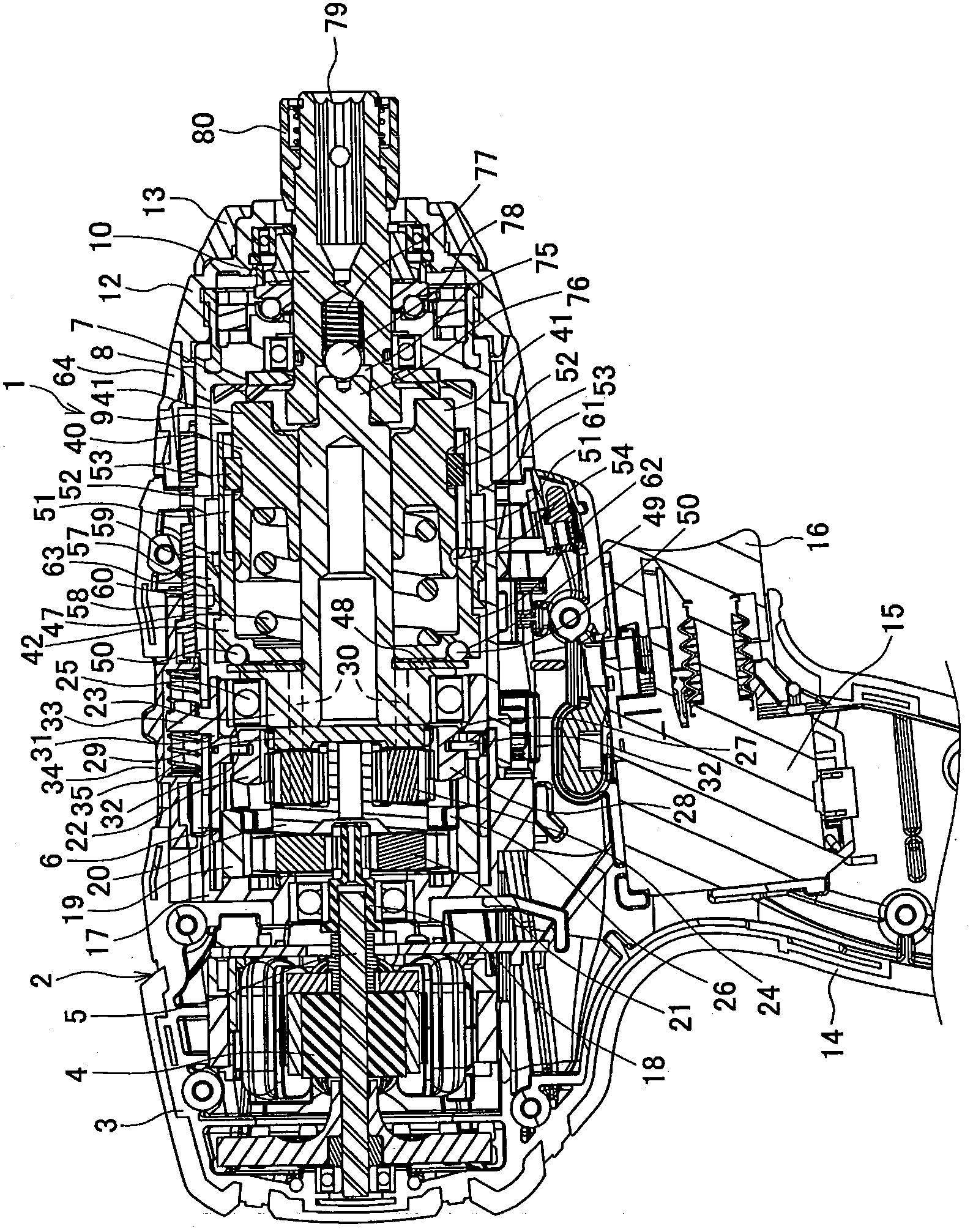
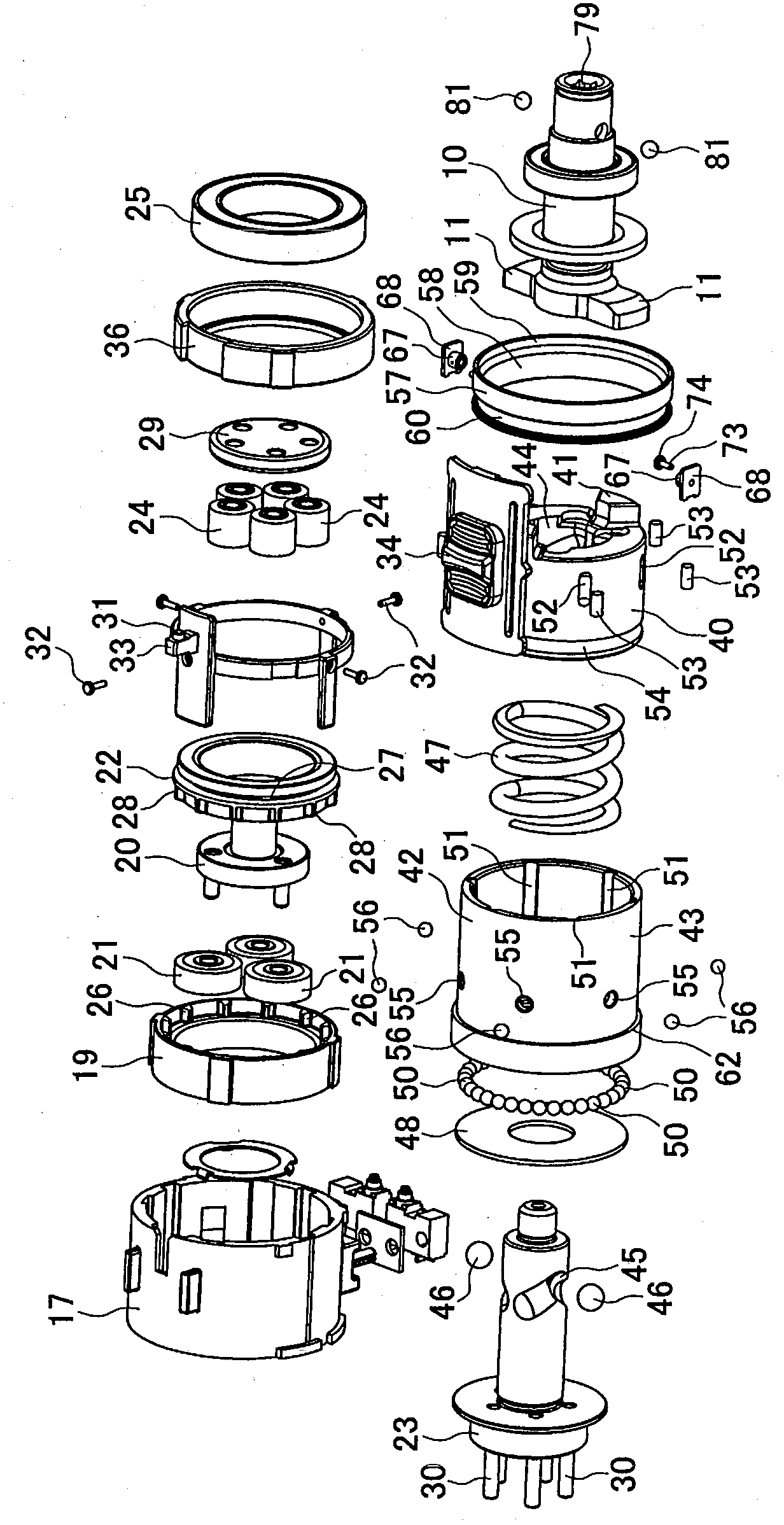
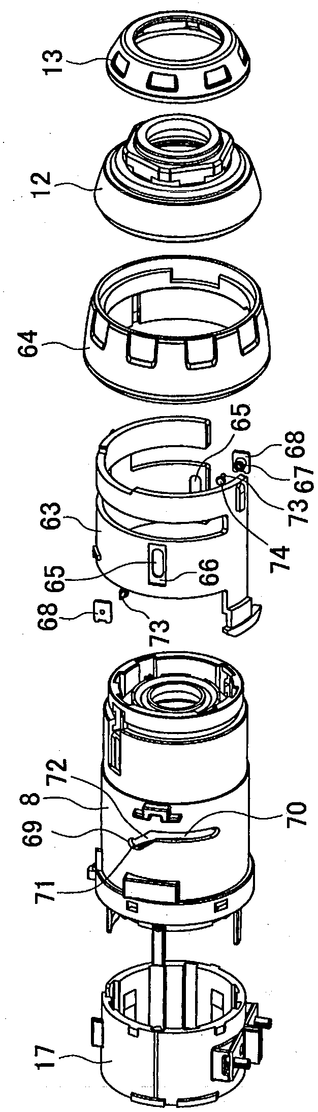
[0020] figure 1 shows an impact screwdriver 1 as an example of an impact tool, figure 2 A part of the internal mechanism of the impact screwdriver 1 is shown. The impact screwdriver 1 has a main body case 2 formed by assembling left and right half shells 3, 3, and can be viewed from the rear (with figure 1 Starting from the right side as the front), a motor 4 , a planetary gear reduction mechanism 6 , and a main shaft 7 are respectively housed in the main body casing 2 . In addition, a cylindrical inner case 8 accommodating the main shaft 7 and the impact mechanism 9 is attached to the front portion of the main body case 2 , and an anvil 10 arranged coaxially in front of the main shaft 7 is rotatably supported by the inner case 8 . and the front housing 12 fixed to the front end of the inner housing 8, and the anvil 10 protrudes forward. 13 is a rubber ring-shaped damper fitted to...


PUM


Abstract

The invention provides an impact tool which realizes a drill mode with low cost and small size structure. In an impact tool (1), a hammer is divided into an inner-side main hammer (40) engageable with or disengageable from an anvil (10) and an outer-side sub hammer (42) having a peripheral wall (43) covering an outer periphery of the main hammer (40) and formed as a separate member. The sub hammer (42) is rotatably disposed in a rearward position, and the peripheral wall (43) is engageable with the main hammer (40) so that the main hammer (40) and the sub hammer (42) are unitarily rotatable. A connecting member (56) is disposed between the main hammer (40) and the peripheral wall (43) in such a manner as to be movable between a connecting position and a disconnected position using a switching device. When the connecting member (56) is moved in the connecting position, a drill mode is selected, in which retraction of the main hammer (40) is restricted.

Description

technical field [0001] The present invention relates to an impact tool such as an impact driver that generates rotational impact force by engaging and disengaging a hammer with an anvil protruding forward of a casing. Background technique [0002] An impact tool such as an impact screwdriver has a main shaft that is rotated by a motor in a housing, a hammer that is fitted on the main shaft, and is connected by a ball that fits with the main shaft and the hammer by straddling a groove provided on the main shaft and the hammer. A claw is protrudingly provided on the front surface of the hammer; an anvil, which is coaxial with the main shaft, is supported by the housing and can rotate, and the front end of the anvil for installing the tool head protrudes to the front of the housing; An arm is radially formed at the end, and a coil spring urges the hammer to an advanced position where the claw and the arm engage in the rotation direction. That is, when the torque of the anvil i...

Claims


Application Information

Patent Timeline
Patent Type & Authority Applications(China)
IPC IPC(8): B25F5/00B25B21/02
CPCB25B21/02B25B21/00
Inventor 平林德夫杉本学
Owner MAKITA CORP
Why Eureka
Try Eureka