Bridge crane

一种桥式起重机、主桁梁的技术,应用在行走的桥式起重机、起重机、小车的起重机等方向,能够解决危险、绳索松弛度危险、耗费卷扬机构时间等问题,达到减小尺寸、提升工作精确的效果

Active Publication Date: 2014-11-19
KONECRANES GLOBAL
View PDF6 Cites 4 Cited by
  • Summary
  • Abstract
  • Description
  • Claims
  • Application Information

AI Technical Summary

Problems solved by technology

When the load is first secured to the hoist hook during the hoisting phase, it always takes some time for the hoisting mechanism before the slack rope caused by sagging is tensioned
This can be dangerous if not prepared for this, slack in the rope caused by sagging is dangerous in installation work where the crane is used for precision lifting

Method used


Image

  • Bridge crane
  • Bridge crane
  • Bridge crane

Examples


Embodiment Construction

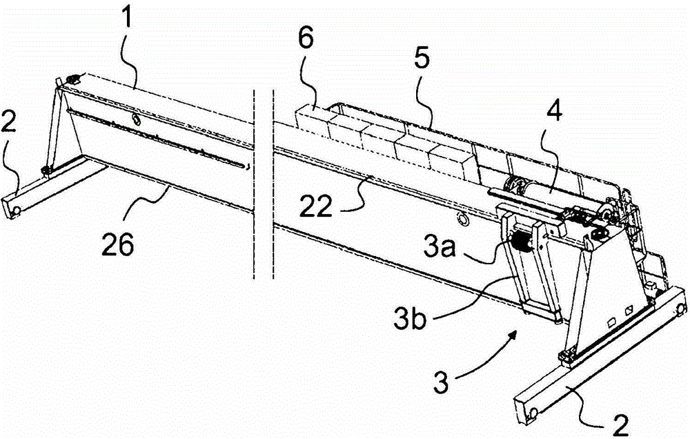
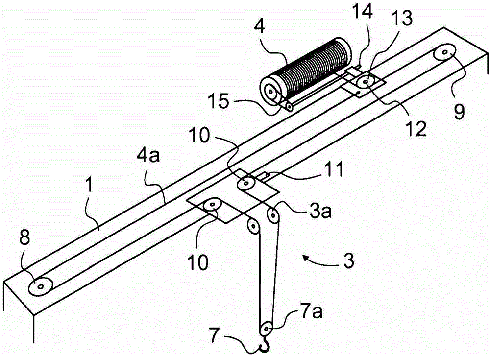
[0024] figure 1 A slanted top view of a simplified and segmented bridge crane according to the present invention is shown, without hoisting ropes, hooks and some other components belonging to the solution, which will be described below. The bridge crane is also called the torsion bridge crane, and it includes a main girder 1, at both ends of the main girder 1, there are end slides 2, which are provided with at least rails Wheel and traveling mechanism. The hoisting tackle 3 is assembled to be combined with the first side of the main girder, and the trolley travels in a lateral direction relative to the traveling direction of the main girder 1 on the first side of the main girder. The hoisting trolley 3 includes a pulley 3a for hoisting the rope and a frame member provided with legs 3b. The frame member abuts on the guide rails 22 and 26 along the longitudinal direction of the main girder, which is at the top of the main girder 1. And on the bottom edge of the first side of the...


PUM


Abstract

The object of the invention is a bridge crane, which comprises a main girder, which is fitted to travel supported by end carriages essentially at both ends and which bridge crane further comprises a hoisting trolley traveling supported by the main girder and a rope drum mounted on bearings to rotate in an essentially stationary position, from which rope drum the hoisting rope is guided to a hook traveling along with the hoisting trolley. The hoisting rope is supported from below for at least a part of its essentially horizontal section.

Description

Technical field [0001] The object of the present invention is a bridge crane, which includes a main truss girder assembled to be supported by end slides to travel, and the end slides are approximately at the two ends of the main truss girder , The bridge crane further includes a hoisting block and a rope drum, the hoisting block is supported by the main girder to travel, and the rope drum is mounted on a bearing to be in a substantially stationary position Rotating, the hoisting rope is guided from the rope winding drum to the hoisting hook part, and the hoisting hook part travels together with the hoisting tackle. Background technique [0002] The prior art bridge crane usually includes two main truss beams separated from each other by a certain distance and a trolley with a hoisting mechanism of the crane, the mechanism travels with the trolley, and the trolley is assembled into a track on the top of the truss beam Move on. One of the problems in this solution is that it is e...

Claims


Application Information

Patent Timeline
Patent Type & Authority Patents(China)
IPC IPC(8): B66C17/00
CPCB66C17/00B66C13/10B66C19/00
Inventor T·林德伯格
Owner KONECRANES GLOBAL
Why Eureka
Try Eureka