
GNSS-based automatic monitoring device for transmission line tower inclination

A transmission line tower, automatic monitoring technology, applied in the field of satellite geodesy, can solve the problems of affecting the monitoring results, the number of satellites cannot meet the positioning requirements, and difficult wiring

Active Publication Date: 2014-10-29
ANHUI SUN CREATE ELECTRONICS
View PDF4 Cites 0 Cited by
  • Summary
  • Abstract
  • Description
  • Claims
  • Application Information

AI Technical Summary

Problems solved by technology

However, the GPS method is easily affected by various external factors on the project site, which leads to the blocking of visible satellites, which seriously affects the monitoring results, and even makes the number of satellites unable to meet the positioning requirements, and cannot perform dynamic deformation monitoring.
In terms of monitoring data transmission, wired and wireless methods can be used. The wired method is expensive to wire, and it is difficult to wire in some places
With the development of wireless communication, wireless data transmission technologies such as GPRS, CDMA, and GSM are increasingly mature, providing a means of wireless data transmission for automatic monitoring systems (such as geological disaster monitoring systems), and GPRS, CDMA, and GSM are also widely used at home and abroad. However, for some areas with underdeveloped communication, or in areas where communication facilities have been damaged by geological disasters such as earthquakes and mountain torrents, these conventional wireless communication methods cannot play a role

Method used


Image

  • GNSS-based automatic monitoring device for transmission line tower inclination
  • GNSS-based automatic monitoring device for transmission line tower inclination
  • GNSS-based automatic monitoring device for transmission line tower inclination

Examples


Embodiment Construction

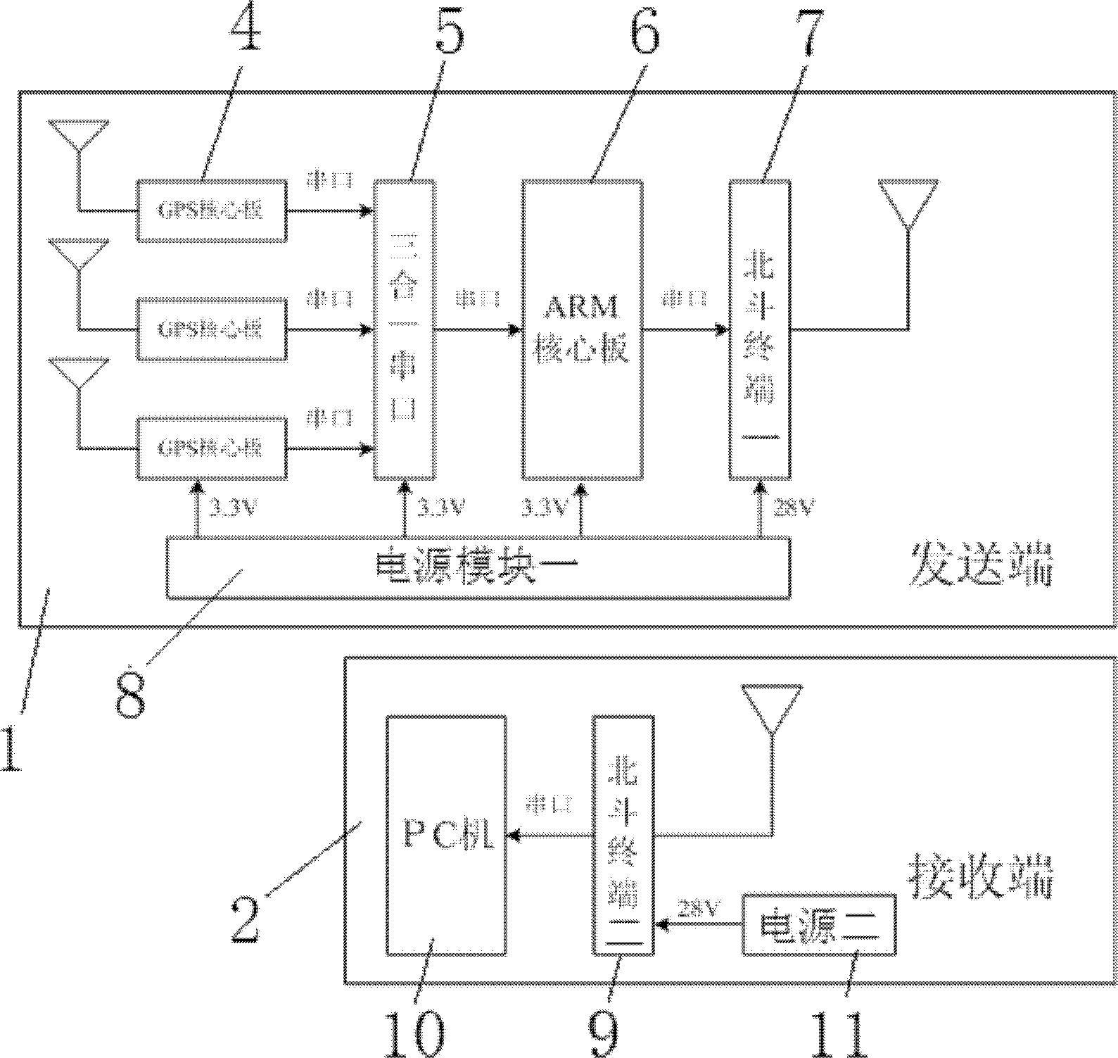
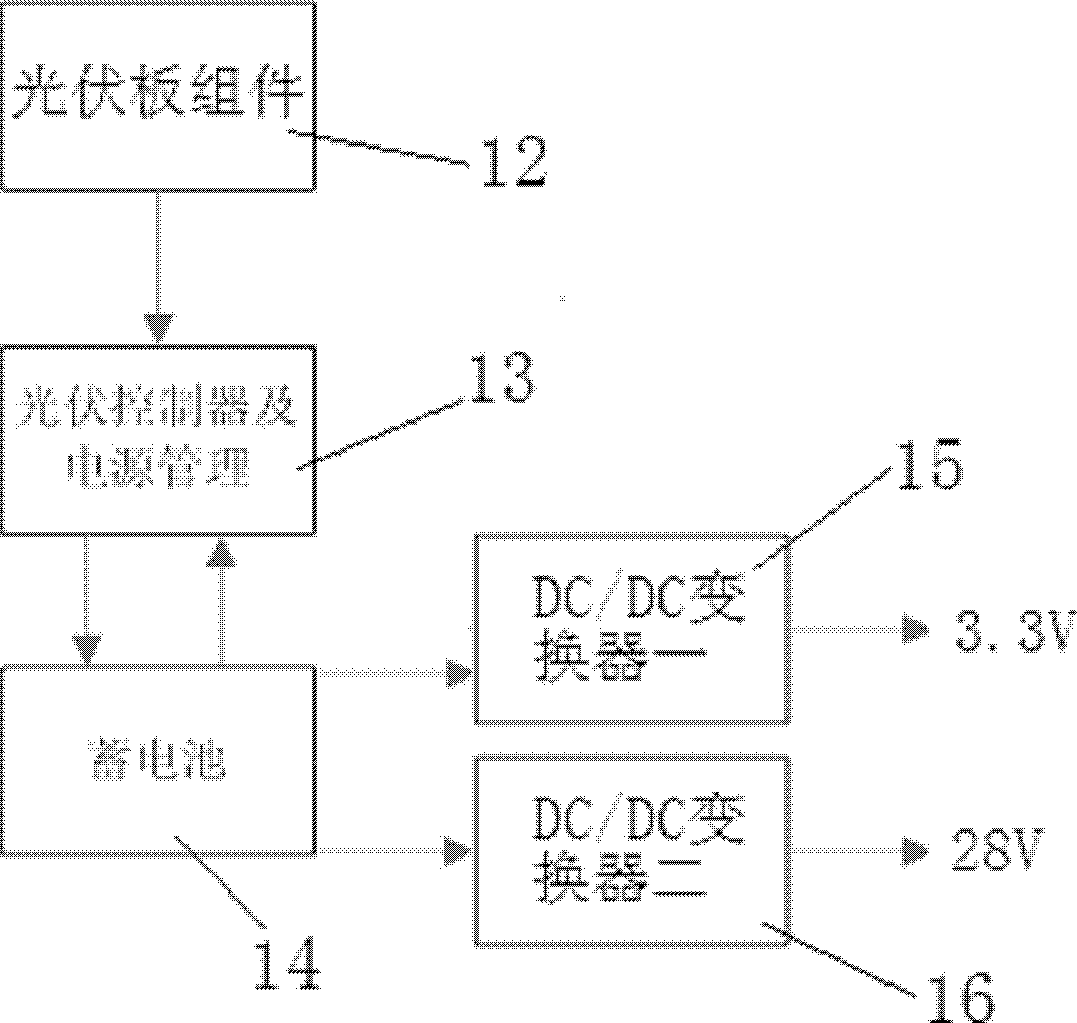
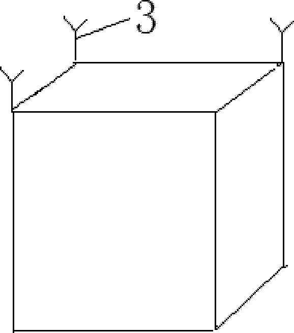
[0015] The GNSS-based device for automatically monitoring the inclination of transmission line towers includes a transmitter 1 and a receiver 2. The transmitter 1 includes three identical GPS modules, an ARM core board 6, a Beidou terminal-7, a power module-8, and a GPS module. Including a GPS antenna 3 and a GPS core board 4, the three GPS antennas 3 are respectively installed on three corner points on the top of the transmission line tower, and the output ends of the three GPS core boards 4 are connected to the ARM core board 6 through a three-in-one serial port 5 Communication connection, the ARM core board 6 is connected to the Beidou terminal-7, the power module 8 can output multiple DC voltages, and each voltage output terminal is connected to the GPS core board 4, the three-in-one serial port 5, and the ARM core board 6 respectively , Beidou terminal 17 connected; receiving end 2 includes Beidou terminal 2 9, PC 10, power module 2 11, Beidou terminal 2 9 communicates wit...


PUM


Abstract

The invention discloses a device for automatic monitoring of the inclination of a power transmission tower based on GNSS, which comprises a sending end, and a receiving end; the sending end comprises three same GPS modules, an ARM core plate, a big dipper terminal one, and a power supply module one; the GPS module comprises a GPS antenna, and a GPS core plate; the three GPS antennae are respectively mounted on three corner points of the power transmission tower; output terminals of the three GPS core plates are in communication connection with the ARM core plate through a three-in-one serial port; the ARM core plate is in communication connection with the big dipper terminal one; the power supply module one can output multipath DC voltage; each voltage output terminal is respectively connected with the GPS core plate, the three-in-one serial port, the ARM core plate, and the big dipper terminal one; the receiving end comprises a big dipper terminal two, a PC, and a power supply module two; the big dipper terminal two is in communication connection with the PC; a DC voltage output terminal of the power supply module two is connected with the big dipper terminal two. The invention can automatically monitor the deformation of a deformable body, transmit monitoring results to a data management center in real time, and automatically carry out early warning.

Description

technical field [0001] The invention belongs to the technical field of satellite geodesy, and in particular relates to a GNSS-based device for automatically monitoring the inclination of transmission line towers. Background technique [0002] With the rapid development of social productivity in recent years, the demand for buildings of human beings presents a trend of complexity and diversification. A variety of super high-rise buildings, long-span bridges, large industrial chimneys, TV towers and other modern large-scale buildings continue to emerge. . These large buildings play a huge role in the entire national economy, once they have a disaster accident, it will lead to huge loss of life and property. [0003] The dynamic deformation monitoring of large-scale engineering structures can grasp the deformation of engineering structures in real time, so that corresponding measures can be taken before accidents to avoid disasters, and at the same time, it can evaluate the sa...

Claims


Application Information

Patent Timeline
Patent Type & Authority Patents(China)
IPC IPC(8): G01C9/00G01C9/04
Inventor 陶庭叶孟宪伟水孝敏曾洁王宇李美玲周同英王世臣赵娟
Owner ANHUI SUN CREATE ELECTRONICS
Learn More