
Stereo imaging device

A technology for stereoscopic imaging and image processing, which is applied in stereophotography, optics, instruments, etc., can solve problems such as the miniaturization and lightness of the stereoscopic imaging device, the complex structure of the lens module, etc., and achieve a simple structure and reduce the number of driving devices. Effect

Inactive Publication Date: 2016-04-27
RUGAO TIANAN ELECTRIC TECH
View PDF4 Cites 1 Cited by
  • Summary
  • Abstract
  • Description
  • Claims
  • Application Information

AI Technical Summary

Problems solved by technology

[0003] However, the movement of each lens needs to be driven by an additional driving device, such as a motor and related structures, which makes the structure of the lens module more complicated, which is not conducive to the miniaturization and portability of the stereo imaging device

Method used


Image

  • Stereo imaging device
  • Stereo imaging device
  • Stereo imaging device

Examples


Embodiment Construction

[0019] The embodiments provided by the present invention will be further described in detail below in conjunction with the accompanying drawings.

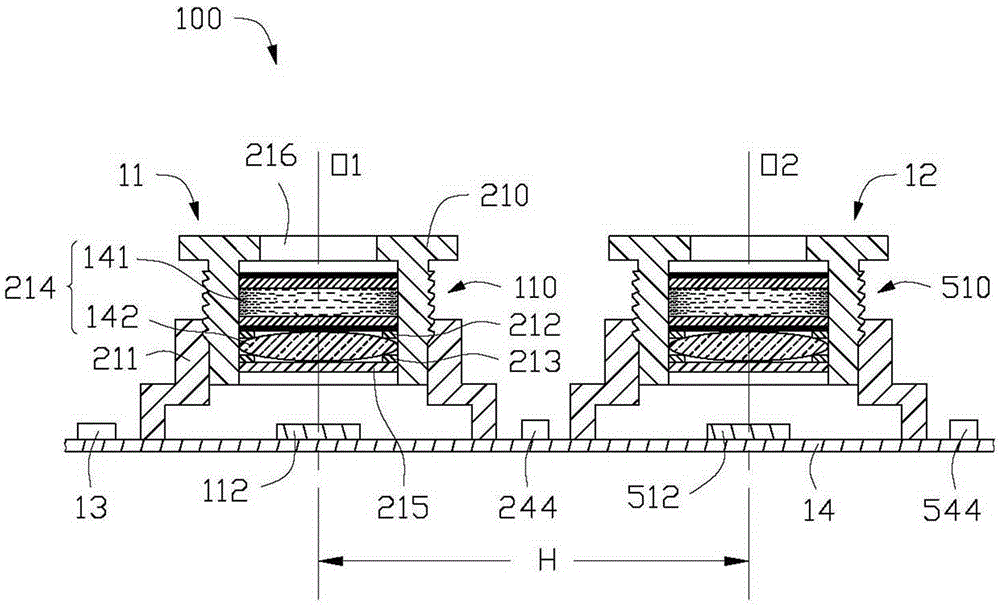
[0020] Please also refer to Figure 1 to Figure 5 The stereo imaging device 100 provided in the first embodiment of the present invention includes two imaging units 11 and 12 spaced apart from each other (hereinafter referred to as the first imaging unit 11 and the second imaging unit 12), electrically connected to the two Image processing unit 13 and circuit board 14 of image capturing units 11 and 12.

[0021] The first image capturing unit 11 includes a lens module 110 and an image sensor 112 located on the image side of the lens module 110 . The lens module 110 includes a lens barrel 210 , a lens base 211 , a first spacer 212 , a second spacer 213 , a lens group 214 , an infrared cut filter 215 and a driving unit 244 . The lens group 214 includes a liquid crystal lens 141 and an optical lens 142 , and the driving unit 244 is ...


PUM


Abstract

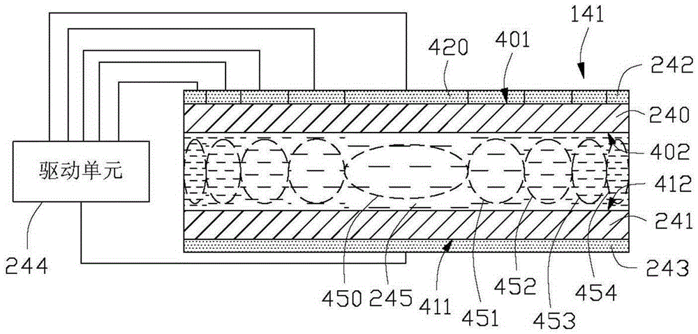
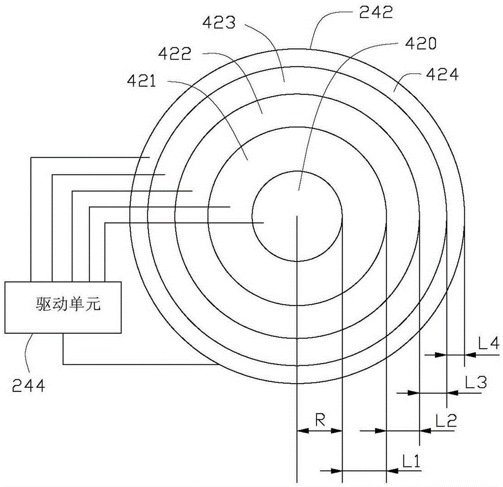
The invention relates to a three-dimensional imaging device, which includes two imaging units and a processing unit, each imaging unit includes a lens module and a sensor, the lens module includes a liquid crystal lens and a driving unit, and the liquid crystal lens includes a first light-transmitting substrate, a second Two light-transmitting substrates, a first electrode layer, a second electrode layer, and a liquid crystal layer, the first electrode layer and the second electrode layer are respectively arranged on the first light-transmitting substrate and the second light-transmitting substrate, and the first electrode layer includes a plurality of The ring electrode, the liquid crystal layer includes a plurality of ring regions respectively located between the plurality of ring electrodes and the second electrode layer, and the driving unit respectively applies a voltage between the ring electrode and the second electrode layer to change the radial direction of the liquid crystal lens. Its refractive index, the sensor forms an image, and the processing unit receives two images formed by the two sensors and synthesizes a stereoscopic image and controls the drive unit to apply voltage.

Description

technical field [0001] The invention relates to a stereo imaging device. Background technique [0002] A stereo imaging device generally includes a lens module for guiding incident light. The lens module realizes the change of the focal length of the lens module by changing the relative positions of the lenses in the lens module, so that the scene in the image can be enlarged or reduced. [0003] However, the movement of each lens needs to be driven by an additional driving device, such as a motor and related structures, which makes the structure of the lens module more complicated, which is not conducive to the miniaturization and portability of the stereo imaging device. Contents of the invention [0004] In view of this, it is necessary to provide a stereo imaging device with a variable focus lens module and a simple structure, so as to facilitate the miniaturization and portability of the stereo imaging device. [0005] A stereoscopic imaging device, which includes t...

Claims


Application Information

Patent Timeline
Patent Type & Authority Patents(China)
IPC IPC(8): G03B35/02G02F1/29G02F1/133G02F1/1343
Inventor 陈杰良
Owner RUGAO TIANAN ELECTRIC TECH
Learn More