
Anti-electric shock protection structure and high voltage equipment with same

A technology of high-voltage equipment and protective structure, applied in the field of electric shock-proof structure design, can solve the problems of increasing the difficulty and cost of design and manufacture, unable to be inserted, and difficult to replace, etc., and achieve the effect of eliminating the danger of electric shock

Active Publication Date: 2013-01-02
SHANGHAI E PROPULSION AUTO TECH +1
View PDF3 Cites 6 Cited by
  • Summary
  • Abstract
  • Description
  • Claims
  • Application Information

AI Technical Summary

Problems solved by technology

[0005] The disadvantages of this method include that when opening the high-voltage junction box, since the output of the high-voltage power has not been disconnected after opening the box cover and disconnecting the low-voltage connector, between disconnecting the connector and disconnecting the high-voltage power There is a time difference, so there is still a risk of high-voltage electric shock; in addition, when the cover is installed in the box body, the low-voltage connector is located inside the junction box, and maintenance or testing personnel cannot immediately observe the low-voltage connector located inside the high-voltage junction box, so there is The two low-voltage connectors may be staggered and cannot be plugged together, and may even cause the two low-voltage connectors to damage each other and are not easy to replace
[0006] In order to solve the above problems, some people proposed to design and install guiding structures on existing high-voltage equipment such as high-voltage junction boxes, etc., but this cannot completely solve the danger of high-voltage electric shock and will cause the structure of high-voltage junction boxes to be too complicated and increase the design , manufacturing difficulty and cost
In addition, the design of this guide structure generally needs to completely abandon the existing low-voltage connectors and carry out new development, resulting in increased design and manufacturing costs

Method used


Image

  • Anti-electric shock protection structure and high voltage equipment with same
  • Anti-electric shock protection structure and high voltage equipment with same
  • Anti-electric shock protection structure and high voltage equipment with same

Examples


Embodiment Construction

[0026] A specific embodiment according to the present invention will be described in detail below with reference to the accompanying drawings. It should be understood that these drawings are only for the purpose of illustration, and are not intended to limit the protection scope of the present invention. The following description should be understood as a preferred embodiment or example of the technical solution of the present invention, the purpose of which is to describe the technical principle of the present invention more clearly, without intending to limit the protection scope of the present invention.

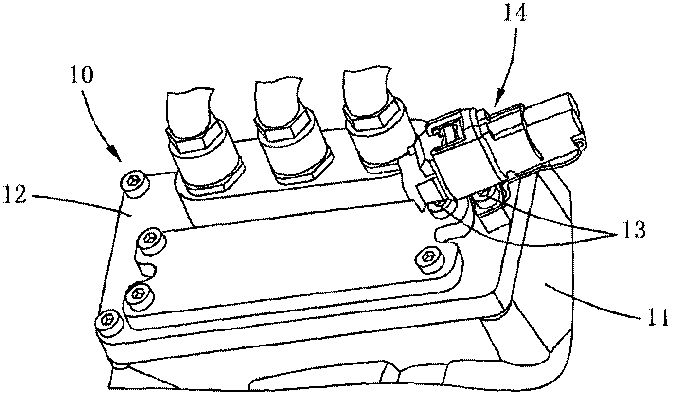
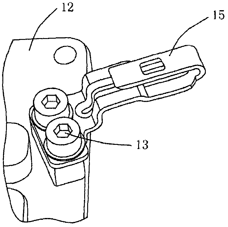
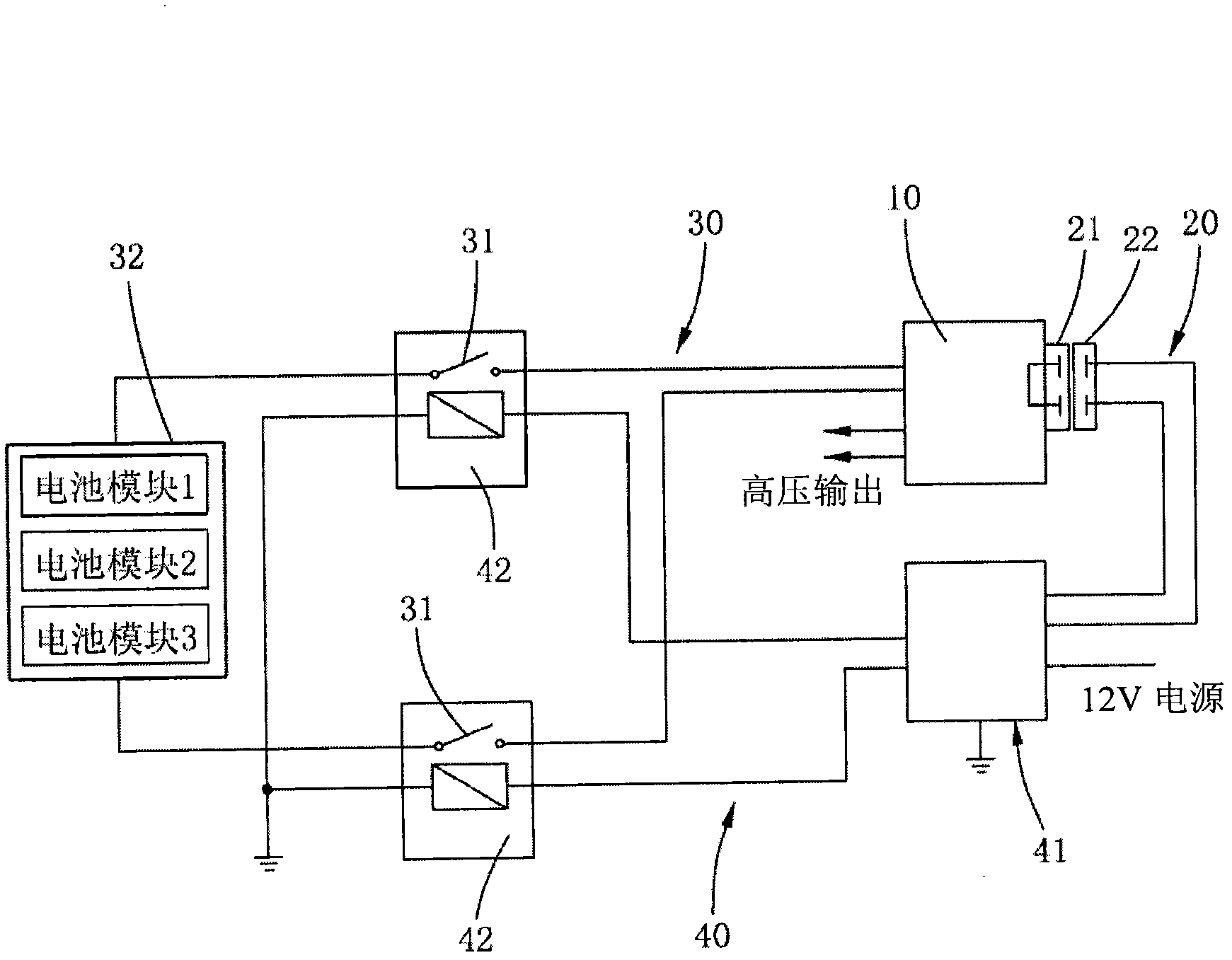
[0027] figure 1 An embodiment of the protection structure against electric shock according to the present invention is schematically shown, which is installed on high-voltage equipment. The high-voltage equipment 10 (such as a high-voltage junction box, etc.) includes a box body 11 and a box cover 12, which can effectively seal the conductors and components with high vol...


PUM


Abstract

The invention relates to an anti-electric shock protection structure for high voltage equipment and the high voltage equipment. A box body of the high voltage equipment is provided with an openable box cover, and the box cover is locked at a closed position by a mechanical connection piece relative to the box body. The anti-electric shock protection structure comprises a low voltage loop and a socket connector, wherein the on-off state of at least one place of a high voltage loop in the high voltage equipment is controlled by a controller through the on-off of the low voltage loop; the socket connector is arranged on the high voltage equipment and shields the mechanical connection piece; the low-voltage loop is conducted through wires arranged in the connector; and when the connector is taken off, the low voltage loop is opened. The above technical scheme has the advantages that electric shock hazard is eliminated, the design, manufacture and use are facilitated, and the cost is effectively reduced.

Description

【Technical field】 [0001] Generally speaking, the present invention relates to the design field of electric shock protection structure of high voltage equipment; more specifically, the present invention relates to an electric shock protection structure and a high voltage equipment with the electric shock protection structure. 【Background technique】 [0002] In many electrical environments, such as electric vehicles, when maintaining or testing high-voltage equipment, it is necessary to first open the high-voltage equipment (such as a high-voltage junction box, etc.). In order to prevent the high-voltage equipment from being opened by maintenance or testing personnel or after the high-voltage equipment is opened, a set of low-voltage connectors that cooperate with each other is generally used as an anti-shock protection device for high-voltage equipment. [0003] Take the high voltage junction box as an example. In the high-voltage junction box of the prior art, the anti-shoc...

Claims


Application Information

Patent Timeline
IPC IPC(8): H02B1/14
Inventor 朱道平
Owner SHANGHAI E PROPULSION AUTO TECH
Learn More