
Fitted Roofing Material, Cleat, And Fitted Roof Structure

A technology of fitting and spreader, applied in the direction of roof, building structure, roof covering layer, etc., can solve the problems of the influence of the fitting state, changing the setting height of the spreader 31, etc.

Inactive Publication Date: 2013-01-02
JFE GALVANIZING & COATING CO LTD
View PDF6 Cites 8 Cited by
  • Summary
  • Abstract
  • Description
  • Claims
  • Application Information

AI Technical Summary

Problems solved by technology

Since the heat insulating material affects the fitting state of the roofing material 1 and the hanger 31, there is a problem that the installation height of the hanger 31 needs to be adjusted, and there is also a problem that the installation height of the hanger 31 needs to be changed regardless of the presence or absence of the heat insulating material. The problem

Method used


Image

  • Fitted Roofing Material, Cleat, And Fitted Roof Structure
  • Fitted Roofing Material, Cleat, And Fitted Roof Structure
  • Fitted Roofing Material, Cleat, And Fitted Roof Structure

Examples


Embodiment Construction

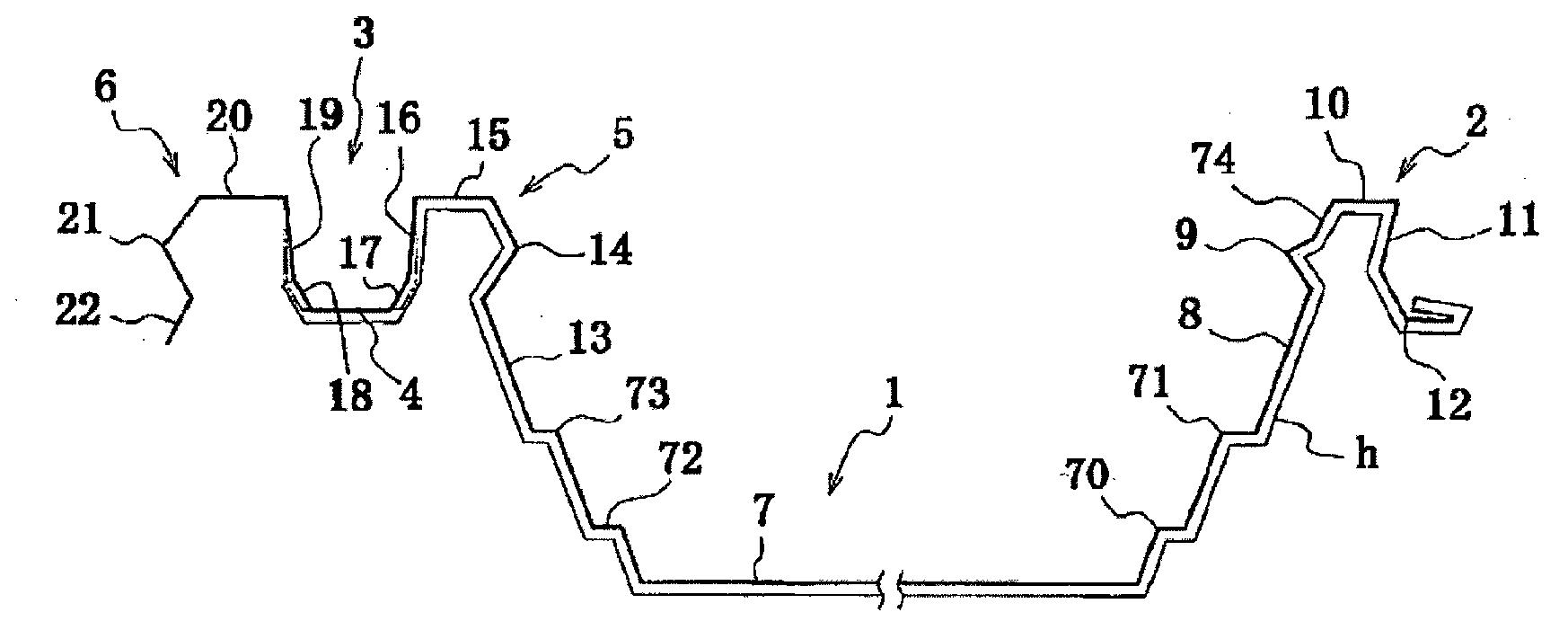
[0036] Hereinafter, the form for implementing this invention is demonstrated in detail based on drawing. Such as figure 2 As shown, the roofing material 1 according to one embodiment of the present invention is composed of a metal plate, and includes forward-inclination side fitting portions 2 formed in concavo-convex shapes along the widthwise side ends of the roofing material 1 and sleeve side fitting portions. The sleeve-side fitting portion 3 has two convex portions 5, 6 connected by the sleeve-side central concave portion 4 serving as the bottom. In the roofing material 1, the forward-inclination side fitting portion 2 of one roofing material 1 is fitted into a hanger 31 according to an embodiment of the present invention described later, and further, the sleeve-side fitting portion 3 of the other roofing material 1 is The two convex parts 5 and 6 are fitted to the hanger 31 and the forward-inclination-side fitting part 2 . Thus, the roofing material 1 is sequentially ...


PUM


Abstract

Provided is a roofing material such that during construction, the back surface of the roofing material is not susceptible to damage and heat insulation material does not peel away from the back surface. The fitted roofing material is obtained by bending a scooping-side fitting element and a capping side fitting element along both edges of a rectangular main plate section of the roofing material in the widthwise direction. Therein, the capping-side fitting element is configured by interconnecting a capping-side upward-sloping section, which is formed at a position extending from the main plate section, a substantially horizontal capping-side central recessed section, which is formed at a position extending from the capping-side upward-sloping section, and a capping-side first protruding section and a capping-side second protruding section, which are positioned on both sides of the capping-side central recessed section so as to sandwich the capping-side central recessed section therebetween. The first protruding section comprises a capping-side first fitting-cog section, which is formed at a position extending from the capping-side upward-sloping section, a capping-side first top part, which extends substantially horizontally at a position extending from the capping-side first fitting-cog section, a capping-side first downward-sloping part, which is bent from the end of the capping-side first top part, and a capping-side first inclined part, which is formed at the edge of the capping-side first downward-sloping part. The capping-side first downward-sloping part of the first protruding section is inclined slightly from the vertical so as to slope downwards towards the central recessed section.

Description

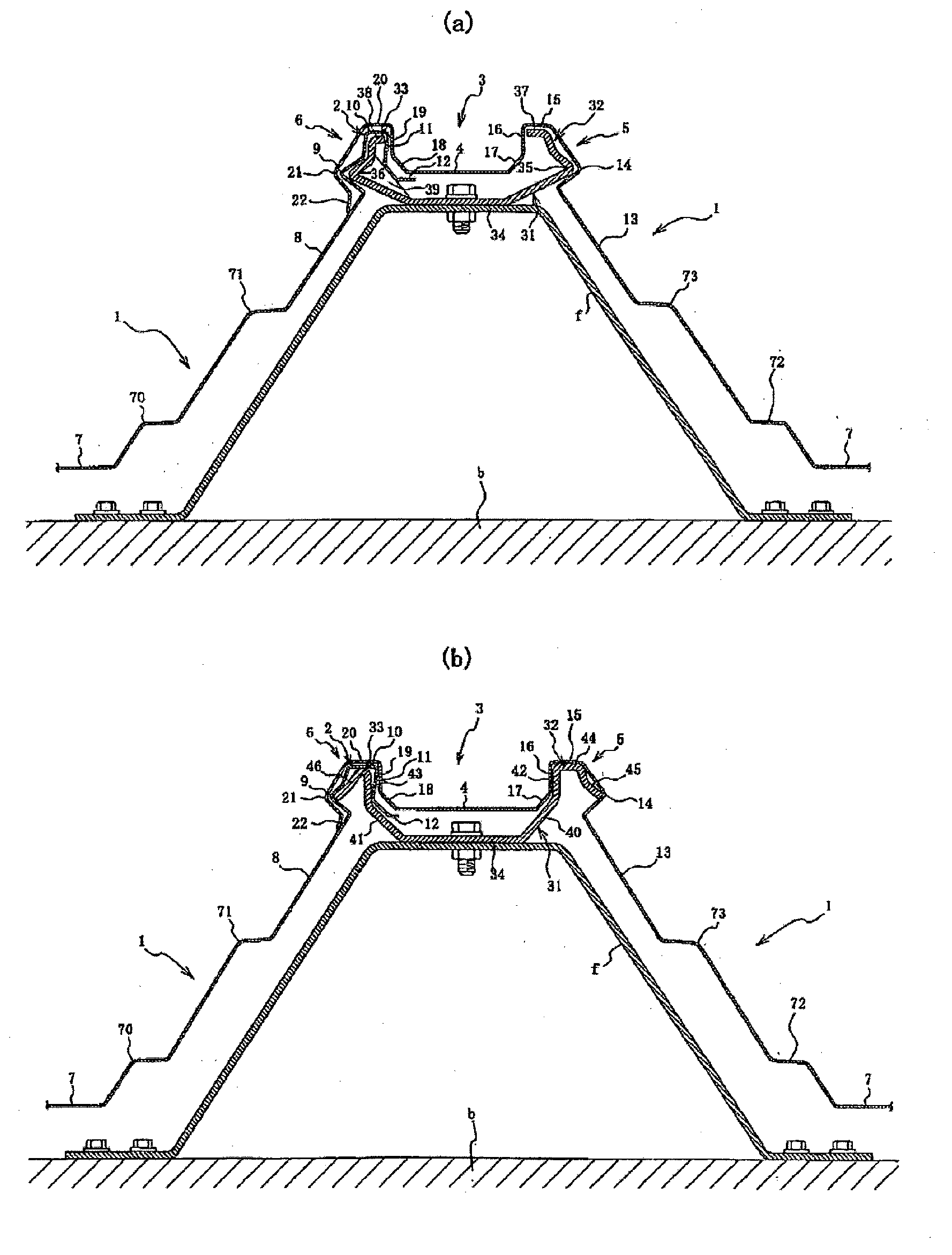
technical field [0001] The present invention relates to an improved fitted roof material, a hanger for fitting and fixing the roof material, and a fitted roof structure using the roof material and the hanger, which have been improved so that roof repair can be performed easily and firmly. Background technique [0002] Conventionally, as a method of repairing the roof, such as figure 1 In the construction methods shown in (a) and (b), first, hangers 31 are respectively attached via trapezoidal and door-shaped fixing fittings f at regular intervals above the beam b of the roof. Next, the scooping-side connector element 2 is fitted to the first fixing part 32 of the first fixing part 32 and the second fixing part 33 of these spreaders 31, wherein the first fixing part part 32 and second fixing part 33 are provided on both sides in the lateral direction corresponding to the width direction (left and right direction in the figure) of the roofing material 1, and the forward-incli...

Claims


Application Information

Patent Timeline
Patent Type & Authority Applications(China)
IPC IPC(8): E04D3/362E04D3/36E04D3/363E04D3/365
CPCE04D3/363E04D3/30E04D3/351
Inventor 工藤教雄长岐大三
Owner JFE GALVANIZING & COATING CO LTD
Learn More