Planar light source apparatus and display apparatus using same

A technology of light source device and point light source, which is applied in the direction of point light source, plane/plate light guide, light source, etc., can solve the problems of low light utilization efficiency, uneven brightness, uneven light diffusion, etc.

Active Publication Date: 2013-01-02
MITSUBISHI ELECTRIC CORP
View PDF8 Cites 10 Cited by
  • Summary
  • Abstract
  • Description
  • Claims
  • Application Information

AI Technical Summary

Problems solved by technology

[0004] However, in the backlight unit and the display device disclosed in Patent Document 1, the light from the point light source is reflected by the side of the light guide plate, and the light diffuses unevenly to cause uneven brightness. After being emitted, it is reflected by the reflector, so the problem of low light utilization efficiency

Method used


Image

  • Planar light source apparatus and display apparatus using same
  • Planar light source apparatus and display apparatus using same
  • Planar light source apparatus and display apparatus using same

Examples


Embodiment approach 1

[0020] Next, the structure of the display device according to the present invention will be described with reference to the drawings. Parts using the same symbols in each figure represent substantially the same structures.

[0021]

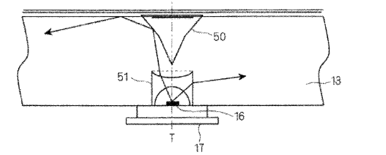
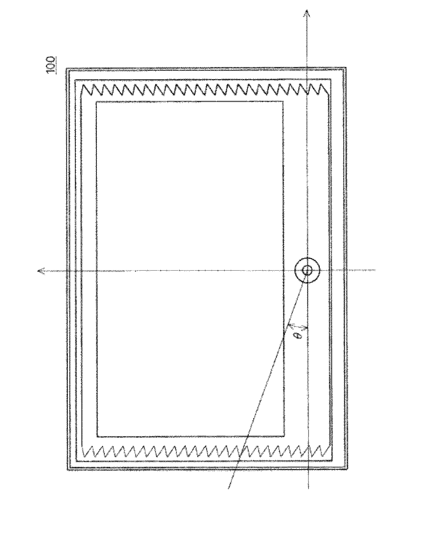
[0022] As shown in FIGS. 1 and 2 , the planar light source device 100 in the embodiment includes a light guide plate 13 that guides light into a planar shape and emits it from the emission surface, and the light guide plate 13 is disposed in a housing 10 having an opening 11. . The light is emitted in a direction having the opening 11, and this direction is taken as an emission direction. FIG. 1 is an exploded view of each component, and FIG. 2 is an overall view seen from the side of the emission surface as the emission direction. In addition, a point light source 16 is arranged in a housing portion formed on the bottom surface of the housing 15 facing the surface having the opening 11 of the housing 10 .

[0023] A diffusion plate (not show...

Embodiment approach 2

[0069]

[0070] The configuration of the planar light source device 100 according to Embodiment 2 will be described below. Here, the parts other than the shape of the second side surface 13 b of the light guide plate 13 are the same as those of the first embodiment, and thus description thereof will be omitted.

[0071] FIG. 7 shows a front view of planar light source device 100 according to Embodiment 2, and FIG. 8 shows a prism detail view of second side surface 13 b of light guide plate 13 in planar light source device 100 . In addition to the specific functions and effects of the planar light source device 100 according to the second embodiment described below, the same functions and effects as those of the planar light source device 100 according to the first embodiment are achieved.

[0072] In Embodiment 1, all the shapes of the prisms are the same, but in Embodiment 2, it is as shown in FIG. 7 .

[0073] That is, the angle between the side B and the reflected point ...


PUM


Abstract

In a planar light source apparatus, light from a point like light source is reflected on a side surface of a light guide plate, preventing light from uniformly spreading and thus causing brightness unevenness, and light exits from the light guide plate and is reflected on a reflection plate, which arises a problem of a low light use efficiency. Disclosed is a planar light source apparatus (100) which is provided with a point like light source (16) and a light guide plate (13) having a rectangular, flat plate shape in a plan view. The light guide plate has a light exiting surface, which faces an opening portion, a pair of second side surfaces (13b), which face each other, and a hole (13c), which is formed on a position where the point like light source (16) is disposed and is opened on an opposite light exiting surface in the vicinity of one first side surface (13a). A ridge line is provided in a direction perpendicular to the light exiting surface (1a), and at least a part of the surfaces of the pair of second side surfaces is a prism having a saw-shaped, repetitive concavo-convex cross section in a direction parallel to the light exiting surface (1a), with the result that light from the point like light source can be efficiently uniformed on the light guide plate, and the brightness unevenness can be prevented.

Description

technical field [0001] The present invention relates to a planar light source device irradiated by a point light source and a display device using the planar light source device. Background technique [0002] In a conventional planar light source device, as disclosed in Patent Document 1, a hole is formed in a light guide plate, and LEDs are arranged in the center of the hole. According to this configuration, the light from the LED can be efficiently incident on the light guide plate, and the brightness of the display portion can be improved. [0003] Patent Document 1: JP-A-2002-109942. [0004] However, in the backlight unit and the display device disclosed in Patent Document 1, the light from the point light source is reflected by the side of the light guide plate, and the light diffuses unevenly to cause uneven brightness. After being emitted, it is reflected by the reflector, so the use efficiency of light is low. Contents of the invention [0005] It is an object ...

Claims


Application Information

Patent Timeline
Patent Type & Authority Applications(China)
IPC IPC(8): F21S2/00F21Y101/02
CPCG02B6/0016G02B6/0018G02B6/0021
Inventor 境诚司
Owner MITSUBISHI ELECTRIC CORP
Why Eureka
Try Eureka