Street lamp illuminating road surface slantwise

A road, irradiated technology, applied in the parts, reflectors, outdoor lighting and other directions of lighting devices, can solve problems such as glare and glare, and achieve the effect of reducing the incidence and avoiding driver glare.

Active Publication Date: 2013-01-09
HANGZHOUSNGOOSE ELECTRICAL
View PDF6 Cites 4 Cited by
  • Summary
  • Abstract
  • Description
  • Claims
  • Application Information

AI Technical Summary

Problems solved by technology

[0004] The technical problem to be solved by the present invention is to solve the problem of glare and glare caused by the existing street lamps to motor vehicle drivers during driving, and proposes a road lamp that obliquely illuminates the road surface, fundamentally avoiding the glare and glare of drivers. occurrence, thereby ensuring driving safety

Method used


Image

  • Street lamp illuminating road surface slantwise
  • Street lamp illuminating road surface slantwise
  • Street lamp illuminating road surface slantwise

Examples


Embodiment 1

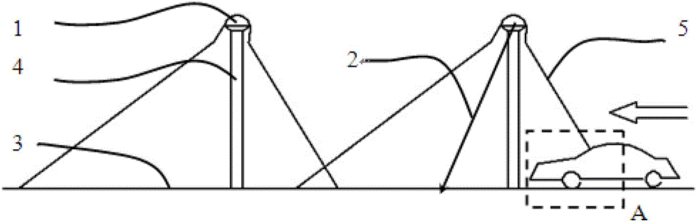
[0025] Such as figure 1 Shown is the structural diagram of Embodiment 1 of the road lamp obliquely irradiating the road surface of the present invention. Most of the light beams emitted by the road lamp 1 (that is, the light beams whose emission direction is the same as the prescribed driving direction of the road) illuminate the road surface 3 along the prescribed driving direction of the road. The projection on the road surface 3 is located on the left side of the light pole 4, and a small part of the light beam (the light beam whose exit direction is opposite to the prescribed driving direction of the road) of the road light 1 shines on the right side of the light pole 4, and its projection on the road surface 3 Located on the right side of light pole 4.

[0026] Wherein, the projection of the center beam of the light beam emitted by the road lamp unit on the road plane is preferably parallel to the prescribed driving direction of the road, and the center beam refers to the bea...

Embodiment 2

[0032] Such as Figure 5 Shown is the structural diagram of Embodiment 2 of the road lamp obliquely illuminating the road surface of the present invention. All the light beams emitted by the road lamp 1 illuminate the road surface 3 along the prescribed driving direction of the road. Obviously, all the emitted light beams will not cause uncomfortable symptoms such as glare and glare to the driver's eyes.

[0033] In summary, the present invention has the advantages of preventing glare and glare, and at the same time, it has the characteristics of simple installation, low maintenance rate, energy saving and the like when in use.


PUM


Abstract

The invention discloses a street lamp illuminating a road surface slantwise. The street lamp comprises a plurality of street lamp units for illumination, wherein all outgoing beams of the street lamp units emit towards the specified traffic direction of the illuminated road surface; or most of the outgoing beams of the street lamp units emits towards the specified traffic direction of the illuminated road surface, the rest of the outgoing beams emits towards the direction opposite to specified traffic direction of the illuminated road surface, and the minimum acute angle formed by the outgoing beams emitting towards the direction opposite to specified traffic direction of the illuminated road surface and the road surface direction is larger than the maximum acute angle formed by the connecting line between each point of an upper edge of a front windshield of a vehicle and eyes of the driver of the vehicle, and the road surface direction. According to the street lamp disclosed by the invention, the occurrence of conditions of dazzling, glare, and the like happed to the driver is fundamentally avoided, thus the traffic safety is ensured.

Description

Technical field [0001] The invention relates to a road lamp, in particular to a road lamp which can avoid glare and glare of motor vehicle drivers. Background technique [0002] In the existing road lighting, in order to increase the lighting range but also to increase the interval between the road lights and save costs, lighting solutions with large angles, high brightness, and high poles are generally adopted. However, the purpose of road lighting is to enable the driver to see the road ahead clearly, to ensure safe and comfortable driving at night. Qualified road lighting must consider the driver's visual requirements, so that the driver can quickly and accurately obtain relevant road traffic information. Most of the existing road lights have large-angle, high-brightness, and high-pole lighting solutions that easily cause the motor vehicle driver as the main traffic participant to have a "glare response" (referring to the unsuitable brightness distribution in the field of vie...

Claims


Application Information

Patent Timeline
IPC IPC(8): F21S8/08F21V7/10F21W131/103F21Y101/02
CPCY02B20/72
Inventor 季杭峰方溁
Owner HANGZHOUSNGOOSE ELECTRICAL
Why Eureka
Try Eureka