An outdoor unit of an air conditioning unit

A technology for outdoor units and air-conditioning devices, applied in air-conditioning systems, space heating and ventilation, household heating, etc., can solve problems such as increased ventilation resistance and poor air flow, and achieve reduced ventilation resistance and increased air supply volume effect

Active Publication Date: 2013-01-16
SANYO ELECTRIC CO LTD
View PDF3 Cites 0 Cited by
  • Summary
  • Abstract
  • Description
  • Claims
  • Application Information

AI Technical Summary

Problems solved by technology

Therefore, since air stagnation occurs at the step, there is a problem that the airflow bec

Method used


Image

  • An outdoor unit of an air conditioning unit
  • An outdoor unit of an air conditioning unit
  • An outdoor unit of an air conditioning unit

Examples


Embodiment Construction

[0034] Hereinafter, embodiments of the present invention will be described with reference to the drawings.

[0035] The air conditioner of this configuration is composed of an outdoor unit 10 and an indoor unit (not shown), and performs a cooling operation and a heating operation by causing refrigerant to flow in a refrigerant circuit formed by connecting refrigerant pipes. The outdoor unit 10 is installed outdoors, exchanges heat with outdoor air, condenses the refrigerant to release heat to the outside air during cooling operation, and evaporates the refrigerant to absorb heat from the outside air during heating operation. In addition, the directions of up and down and left and right described below indicate directions when the outdoor unit 10 is installed and viewed from the front side.

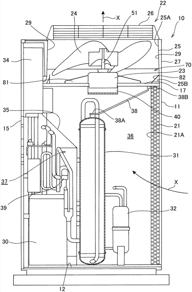
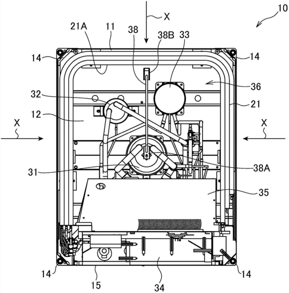
[0036] figure 1 is a side sectional view of the outdoor unit 10 viewed from the right side, figure 2 It is a plan view showing the internal structure of the outdoor unit 10 . The outdo...


PUM


Abstract

The utility model provides an outdoor unit of an air conditioning unit. Ventilation resistance is reduced while air output is increased. The outdoor unit (10) of the air conditioning unit comprises a heat exchanger (21) which is disposed on a bottom plate (12) of a unit housing (11) and at least forms one side of the unit housing (11), an outdoor fan unit (22) disposed on the upper portion of the heat exchanger (21), and a trumpet-shaped port (25) disposed around an impeller-type fan (24) of the outdoor fan unit (22). The trumpet-shaped port (25) comprises an inner wall (29) disposed on the outer side with enlarged opening relative to the inner surface (21A) of the heat exchanger (21). The outdoor unit comprises wind direction plates (81-83) tilting upward from the upper end of the inner surface (21A) of the heat exchanger to the inner wall (29) of the trumpet-shaped port (25).

Description

technical field [0001] The present invention relates to an outdoor unit of an air conditioner of the type that blows air sucked in from the side through a heat exchanger upward by a blower. Background technique [0002] In general, an outdoor unit of an air conditioner is known, which includes a heat exchanger disposed on the bottom plate of the housing and forming at least one side surface of the housing, and an axial flow fan disposed above the heat exchanger. The blower blows the air drawn in through the heat exchanger upwards. In such an outdoor unit, a structure has been proposed in which a heat exchanger is formed into a substantially U-shaped cross-section and arranged on a bottom plate along the three surfaces of the rear side and both side sides of the frame, so as to secure the heat exchange area. It is possible to save the installation area while saving the installation area (for example, refer to Patent Document 1). [0003] Patent Document 1: Japanese Patent L...

Claims


Application Information

Patent Timeline
IPC IPC(8): F24F1/06
Inventor 永富吉成
Owner SANYO ELECTRIC CO LTD
Why Eureka
Try Eureka