Experiment system for corrosion of stray currents in subway

A technique for stray current and corrosion experiments, applied in weather resistance/light resistance/corrosion resistance, measuring devices, instruments, etc., can solve problems such as inability to quantitatively express the relationship between polarization potentials

Inactive Publication Date: 2013-01-16
CHINA UNIV OF MINING & TECH
2 Cites 12 Cited by

AI-Extracted Technical Summary

Problems solved by technology

[0004]Technical problem: the purpose of this invention is to provide a subway stray current corrosion experimental system, which solves th...

Abstract

An experiment system for corrosion of stray currents in a subway belongs to a system for simulating corrosion process of stray currents in a subway. An anode and a cathode of an adjustable direct-current power supply of the experiment system are connected with two different auxiliary electrodes respectively, and the auxiliary electrodes are embedded in the upper surface of a reinforced concrete block. Reinforcing steel bars are distributed at different positions inside the reinforced concrete block. The lower surface of the reinforced concrete block closely contacts with soil medium in a soil box, and steel tubes are disposed in the soil box. Reference electrodes are buried close to the reinforcing steel bars and the steel tubes. Measuring points of the reinforcing steel bars, measuring points of the steel tubes and the reference electrodes are connected with a signal conditioner through wires, and a testing signal is transmitted to a data acquisition device. A pressure signal of the adjustable direct-current power supply is transmitted to the data acquisition device through an electricity transmitter in real time. The data acquisition device transmits the two signals to an upper computer through a serial communication port. The experiment system can effectively simulate the corrosion process of stray currents in a subway, and accordingly capability of estimating corrosion state of a metal structure in a subway system is further increased for experiment preparation.

Application Domain

Weather/light/corrosion resistance

Technology Topic

RebarSteel tube +20

Image

  • Experiment system for corrosion of stray currents in subway
  • Experiment system for corrosion of stray currents in subway

Examples

  • Experimental program(1)
  • Effect test(1)

Example Embodiment

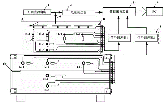
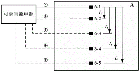
[0018] Example 1: The subway stray current corrosion experiment system includes: an adjustable DC power supply 1, a power transmitter 2, a data acquisition device 3, a host computer 4, a signal conditioner 5, an auxiliary electrode 6, a steel mesh 7, and a reinforced concrete block 8. Reference electrode 9, soil tank 10, steel bar 11 and steel pipe 12. The positive and negative electrodes of the adjustable DC power supply 1 are respectively connected to two different auxiliary electrodes 6, and the auxiliary electrodes 6 are embedded in the upper surface of the reinforced concrete block 8; the reinforcing bars 11 are distributed at different positions inside the reinforced concrete block 8, and six are arranged in total; The lower surface of the concrete block 8 is in close contact with the soil medium in the soil box 10, and five steel pipes 12 with different positions are arranged in the soil box 10; the reference electrode 9 is buried next to the steel bar 11 and the steel pipe 12; The point and the reference electrode 9 are connected to the signal conditioner 5 through wires, and transmit the test signal to the data acquisition device 3; the voltage signal of the adjustable DC power supply 1 is transmitted to the data acquisition device 3 in real time through the power transmitter 2; The device 3 transmits the two-way signals to the upper computer 4 through the serial communication port.
[0019] The size of the reinforced concrete block 8 is 0.850 m×0.675 m×0.267 m (length×width×height), and the composition of the reinforced concrete block 8 is water:stone:sand:cement, and the weight ratio is 8:44:32.5: 15.5; The size of the soil box 10 is 1.000 m×0.850 m×0.675 m (length×width×height), and it is made of insulating wooden boards.
[0020] The adjustable DC power supply 1 applies different voltages to the experimental system through the auxiliary electrode 6, and the current generated in the experimental system is used to simulate the locomotive traction current in the subway system.
[0021] The auxiliary electrodes 6 are made of thin steel sheets, and there are five in total, which are respectively represented as 6-1, 6-2, 6-3, 6-4 and 6-5, and any two auxiliary electrodes have the same adjustable direct current. The positive and negative poles of the power supply 1 are connected, thereby generating four different lengths between the positive pole and the negative pole, which are used to simulate the distances of different power supply sections in the subway system.
[0022] There are a total of six steel bars 11, which are respectively indicated as 11-1, 11-2, 11-3, 11-4, 11-5 and 11-6; four of them have the same depth, but are at the same level as the auxiliary electrode 6 The distances are different, and three of them have different depths, but the horizontal distance is the same as that of the auxiliary electrode 6, all of which are used to simulate the structural steel bars with different distribution positions in the overall track bed or the tunnel sidewall in the subway system.
[0023] The steel pipes 12 have a total of five pipes, which are respectively indicated as 12-1, 12-2, 12-3, 12-4 and 12-5, three of which have the same depth, but are different in horizontal distance from the auxiliary electrode 6, and there are three pipes. The depth is different, but the horizontal distance from the auxiliary electrode 6 is the same, and they are all used to simulate buried metal pipes and lines with different distribution positions in the subway system, such as water pipes, gas pipes and oil pipes.
[0024] The resistivity of the soil medium in the soil box 10 is used to simulate the resistivity of the soil around the metal structure in the subway system.
[0025] The reinforced mesh 7 is used to simulate the drainage mesh of the overall track bed or the side wall of the tunnel in the subway system.
[0026] The reference electrode adopts Mo/MoO reference electrode.
[0027] The distance between different auxiliary electrodes 6, the horizontal length of the steel bar 11 and the steel pipe 12 from the auxiliary electrode 6, the buried depth of the steel bar 11 and the steel pipe 1, the resistivity of the soil medium in the soil box 10 and the voltage of the adjustable DC power supply 1 are respectively It is used to simulate the distance between the power supply interval, the horizontal length of the metal structure from the rail, the buried depth of the metal structure, the soil resistivity and the traction current of the locomotive in the subway system.
[0028] figure 1 For the subway stray current corrosion experimental system. The core of the experimental system is a simulated experimental bench composed of reinforced concrete blocks 8 and soil boxes 10 .

PUM

PropertyMeasurementUnit
Size267.0m
Size0.267 ~ 675.0m

Description & Claims & Application Information

We can also present the details of the Description, Claims and Application information to help users get a comprehensive understanding of the technical details of the patent, such as background art, summary of invention, brief description of drawings, description of embodiments, and other original content. On the other hand, users can also determine the specific scope of protection of the technology through the list of claims; as well as understand the changes in the life cycle of the technology with the presentation of the patent timeline. Login to view more.
Why Eureka
Try Eureka