Blocking inspection method and device for electric-leakage bright spots

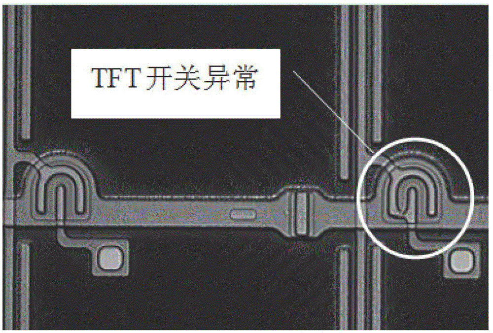
A bright spot and bright spot technology, applied in the field of leakage bright spot detection method and device, can solve problems such as failure to detect leakage bright spot, and achieve the effects of improving defect detection capability, improving yield, and saving costs.

Active Publication Date: 2015-03-25
TCL CHINA STAR OPTOELECTRONICS TECH CO LTD
View PDF2 Cites 0 Cited by
  • Summary
  • Abstract
  • Description
  • Claims
  • Application Information

AI Technical Summary

Problems solved by technology

It can be seen that in the prior art, the cell process of the liquid crystal panel cannot detect potential leakage points caused by damage to the TFT switch.

Method used


Image

  • Blocking inspection method and device for electric-leakage bright spots
  • Blocking inspection method and device for electric-leakage bright spots
  • Blocking inspection method and device for electric-leakage bright spots

Examples


Embodiment Construction

[0043] The technical solutions of the present invention will be further described below in conjunction with the accompanying drawings and specific embodiments. It should be understood that the specific embodiments described here are only used to explain the present invention, not to limit the present invention.

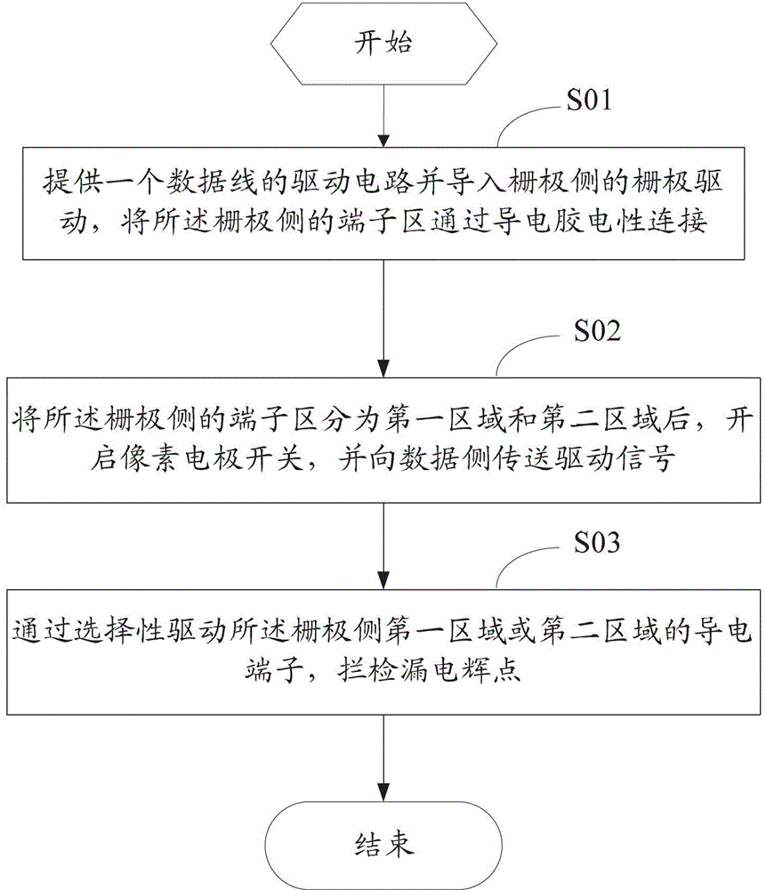
[0044] refer to figure 2 , figure 2 It is a schematic flow chart of an embodiment of the method for blocking and detecting leakage points of electric leakage of the present invention; figure 2 As shown, the electric leakage spot check method of the present invention comprises the following steps:

[0045] Step S01, providing a driving circuit for the data line, and introducing a gate driver on the gate side, and electrically connecting the terminal area on the gate side through conductive glue;

[0046] The invention detects the electric leakage bright spot of the liquid crystal panel in the cell segment. For the VA mode, a driving circuit for the data line is ...


PUM


Abstract

A blocking inspection method and device for electric-leakage bright spots, comprises: providing a driving circuit of a data line and guiding in grid electrode drive of a grid electrode side, electrically connecting a terminal area of the grid electrode side through conducting paste; after dividing the terminal area of the grid electrode side into a first area and a second area, opening a pixel electrode switch, and transmitting driving signals to a data side; and blocking and inspecting the electric-leakage bright spots by selectively driving conducting terminals in the first area or the second area of the grid electrode side. The blocking inspection device for the electric-leakage bright spots, by providing the driving circuit of the data line, enabling the terminal area of the grid electrode side to be electrically connected through the conducting paste, opening the pixel electrode switch, transmitting the driving signals to the data side and blocking and inspecting the electric-leakage bright spots by selectively driving conducting terminals in different areas of the grid electrode side, has the advantage that the electric-leakage bright spots can be blocked and inspected at a Cell section conveniently and fast, so that the defect checkout capability of the system is enhanced, the product yield is increased, leakage is reduced, and the cost is saved.

Description

technical field [0001] The invention relates to the technical field of liquid crystal panels, in particular to a method and a device for detecting electric leakage points. Background technique [0002] The leakage bright spot of TFT-LCD (Thin Film Transistor-Liquid Crystal Display) panel refers to the bright spot formed by the leakage of TFT switch. refer to figure 1 , figure 1 It is a schematic diagram of the abnormal structure of the TFT switch; figure 1 As shown, when the TFT switch is abnormal, bright spots will appear on the LCD panel, which will affect the use effect of the LCD panel. [0003] Considering the detection cost, the existing technology still adopts 1D1G lighting method to detect it in the cell process stage of the liquid crystal panel, that is, to provide a driving circuit for the data line, and whether the conductive terminal electrically connected to the gate side through conductive glue is enabled Cooperate to detect leakage points; but the 1D1G lig...

Claims


Application Information

Patent Timeline
Patent Type & Authority Patents(China)
IPC IPC(8): G09G3/00G02F1/13
CPCG09G3/3648G09G3/006G09G2330/10G02F2001/136254G02F1/136254
Inventor 黄皓李志明潘昶宏
Owner TCL CHINA STAR OPTOELECTRONICS TECH CO LTD
Why Eureka
Try Eureka