
Method of applying light sensor on camera module and terminal equipment

A camera module and light sensor technology, applied in the field of communication, can solve the problems of reducing user experience, unable to keep up with the reaction speed of human eyes, reducing the image effect of the camera, etc., to achieve the effect of improving the image effect

Inactive Publication Date: 2013-01-16
TRULY OPTO ELECTRONICS
View PDF5 Cites 12 Cited by
  • Summary
  • Abstract
  • Description
  • Claims
  • Application Information

AI Technical Summary

Problems solved by technology

[0003] However, at present, the photosensitive IC (integrated circuit, integrated circuit) of most miniature camera modules responds slowly to the ambient brightness and cannot keep up with the reaction speed of the human eye, thereby reducing the image effect of the camera and reducing the user experience.

Method used


Image

  • Method of applying light sensor on camera module and terminal equipment
  • Method of applying light sensor on camera module and terminal equipment
  • Method of applying light sensor on camera module and terminal equipment

Examples


Embodiment Construction

[0020] Embodiments of the present invention will be described in detail below in conjunction with the accompanying drawings.

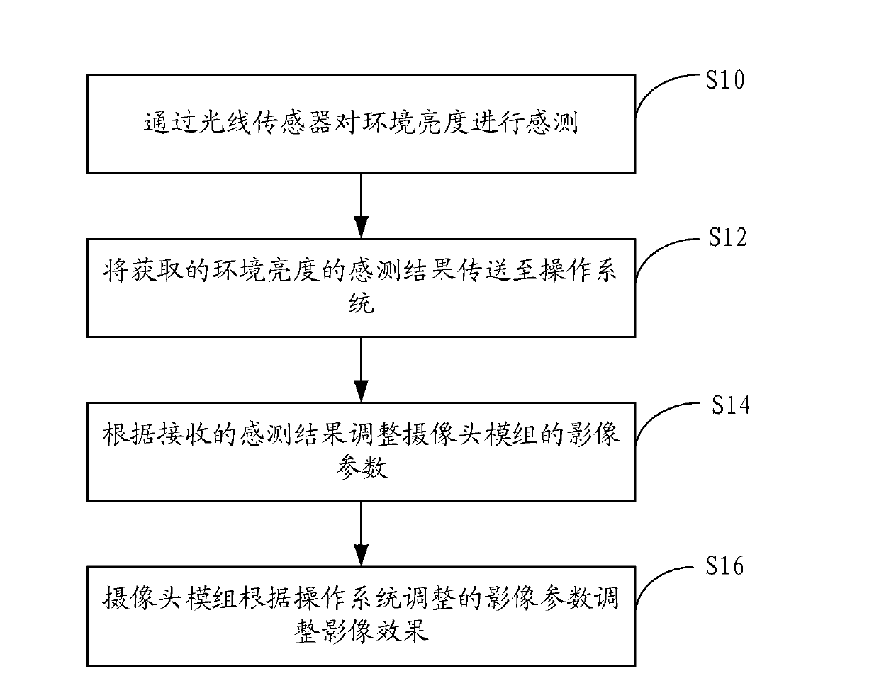
[0021] figure 1 The first flow chart of the method for applying the light sensor to the camera module provided by the embodiment of the present invention.

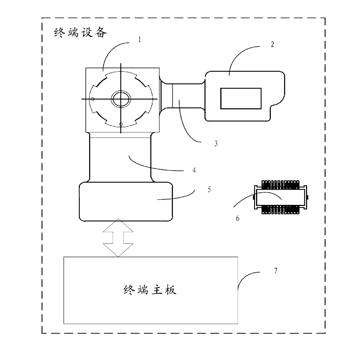
[0022] In this embodiment, the camera module can be applied to a terminal device, and the terminal device can be a mobile phone, a tablet computer or a personal computer. In this embodiment, the camera module is electrically connected to the main board (PCB board) of the terminal device through golden fingers or connectors, and the parameters or functions of the camera module can be adjusted through the operating system platform on the main board of the terminal device. or on. In this embodiment, the camera module may be electrically connected to the light sensor, and the camera module and the light sensor may be electrically connected to the main board of the terminal device through a shared fle...


PUM


Abstract

The invention relates to a method of applying a light sensor on a camera module and terminal equipment, wherein the method comprises: sensing the environmental brightness through the light sensor; sending the obtained environmental brightness sensing result to an operating system of the terminal equipment; adjusting the image parameters of the camera module by the operating system of the terminal equipment according to the received sensing result; and adjusting the image effect by the camera module according to the image parameters adjusted by the operating system so as to improve the image effect of the camera.

Description

technical field [0001] The present invention relates to the communication field, in particular to a method and terminal equipment for applying a light sensor to a camera module. Background technique [0002] With the continuous development of science and technology, more and more consumer terminal devices continue to affect the lives of consumers, such as mobile phones or tablet computers or personal computers. At the same time, consumers are paying more and more attention to various applications on these terminal devices, for example, using the camera of the camera module on the terminal device to take pictures or make video calls. [0003] However, at present, the photosensitive IC (integrated circuit, integrated circuit) of most miniature camera modules responds slowly to the ambient brightness and cannot keep up with the reaction speed of the human eye, thus reducing the image quality of the camera and degrading the user experience. Contents of the invention [0004] ...

Claims


Application Information

Patent Timeline
IPC IPC(8): H04N5/232G01J1/00G01V8/10G06F9/48
Inventor 翁继文李建华
Owner TRULY OPTO ELECTRONICS
Learn More