Clamping device

A technology of a clamping device and an elastic device, which is applied to household refrigeration devices, lighting and heating equipment, household appliances, etc. shaking effect

Active Publication Date: 2015-01-07
HAIER GRP CORP +1
View PDF5 Cites 0 Cited by
  • Summary
  • Abstract
  • Description
  • Claims
  • Application Information

AI Technical Summary

Problems solved by technology

In the patent document disclosed above, the refrigerated storage rack includes a rack body, and several storage boards are arranged in the rack body, and the storage boards divide the rack body into several storage chambers. The front part of the spring piece is an inclined section, and the two inclined sections form a bell mouth forward, so that the box body is clamped and fixed by the spring piece. However, since the spring piece cannot fine-tune the inclination angle of the box itself, Therefore, when in use, the box body and the spring piece cannot always maintain surface contact, so when the drawer is pulled out or inserted, it is easy to cause the box body to shake from side to side

Method used


Image

  • Clamping device
  • Clamping device
  • Clamping device

Examples


Embodiment 1

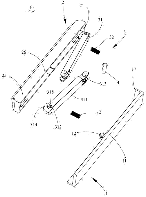
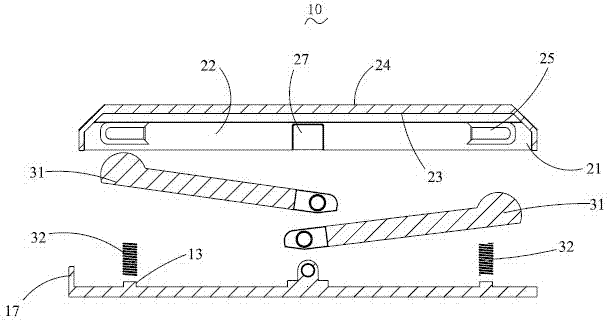
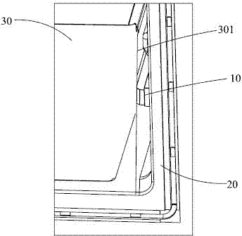
[0020] See Figure 1 to Figure 4 , the clamping device 10 in this embodiment is disposed between the inner wall 20 and the drawer 30 of the refrigerator. The drawer 30 includes side walls 301 . The clamping device 10 includes a base 1 fixed on the inner wall 20 of the refrigerator, a positioning piece 2 arranged opposite to the base 1 and against the side wall 301 of the drawer 30 , and a positioning piece 2 arranged between the base 1 and the positioning piece 2 and holding the positioning piece 2 The elastic device 3 is always in contact with the side wall 301 of the drawer 30 .

[0021] The base 1 includes a base 11 , a fixing portion 12 extending from the base 11 toward the positioning member 2 , a fastening portion 13 and an extension piece 17 . The base sheet 11 is fixed on the inner wall 20 of the refrigerator, and the extension sheet 17 is located outside the elastic device 3 . The height of the fixing portion 12 is higher than that of the fastening portion 13 . Th...

Embodiment 2

[0026] See Figure 5 with Image 6 The difference between the clamping device 10' in this embodiment and the clamping device 10 in the first embodiment is that in this embodiment, the elastic device 5 includes an arc-shaped elastic piece 51 and fixes the elastic piece 51 on the base 1 Fastener 52 on. The elastic piece 51 includes resisting portions 511 respectively located at two ends of the elastic piece 51 and connecting portions 512 for disposing the fastener 52 . The connecting portion 512 is located at the middle section of the elastic piece 51 . The two abutting portions 511 always abut against the positioning member 2 and respectively abut against two sides of the positioning member 2 oppositely.

[0027] The base 1 includes a base plate 11 fixed on the inner wall of the refrigerator (not shown), a supporting column 14 extending from the base plate 11 toward the positioning member 2, and a limiting block formed by protruding outward from the supporting column 14 15....

Embodiment 3

[0029] See Figure 7 The difference between the clamping device in this embodiment and the clamping device 10' in Embodiment 2 is that in this embodiment, the elastic device 6 includes two oppositely arranged and arc-shaped first elastic pieces 61 and second elastic pieces 63 , and fasteners 62 for respectively fixing the first elastic piece 61 and the second elastic piece 63 on the base 1 . The first elastic piece 61 includes a first resisting portion 611 and a first connecting portion 612 respectively located at two ends of the first elastic piece 61 . The second elastic piece 63 includes a second elastic piece 631 and a second connecting portion 632 respectively located at two ends of the second elastic piece 63 . The first abutting portion 611 and the second abutting portion 631 respectively abut against two sides of a positioning member (not shown). Both the first connecting portion 612 and the second connecting portion 632 are fixed on the base 1 by fasteners 62 .


PUM


Abstract

The invention relates to a clamping device arranged between the inner wall of a refrigerator and a drawer. The clamping device comprises a base fixed on the inner wall of the refrigerator, a location piece which is arranged in correspondence to the base and resists against the side wall of the drawer, and an elastic device which is arranged between the base and the locating piece and can keep the locating piece in contacting with the side wall of the drawer all the time. The elastic device of the clamping device provided by the invention can keep the locating piece in contacting with the side wall of the drawer all the time, when the clamping device is arranged between the drawer and the inner wall of the refrigerator, the drawer is prevented from shaking from the left to the right, and so that the locking purpose is achieved.

Description

technical field [0001] The invention relates to a clamping device. Background technique [0002] No. CN 1862193 A on November 15, 2006 disclosed a refrigerated shelf with a spring device. In the patent document disclosed above, the refrigerated storage rack includes a rack body, and several storage boards are arranged in the rack body, and the storage boards divide the rack body into several storage chambers. The front part of the spring piece is an inclined section, and the two inclined sections form a bell mouth forward, so that the box body is clamped and fixed by the spring piece. However, since the spring piece cannot fine-tune the inclination angle of the box itself, Therefore, when in use, the surface contact between the box body and the spring piece cannot always be maintained, so that when the drawer is drawn out or inserted, the box body is likely to shake from side to side. [0003] In view of this, it is necessary to improve the existing device for fixing the d...

Claims


Application Information

Patent Timeline
Patent Type & Authority Patents(China)
IPC IPC(8): F25D25/02
Inventor 王磊陈忠峻费斌毕云龙施文昌夏恩品刘浩泉王晶
Owner HAIER GRP CORP
Why Eureka
Try Eureka