

Foot warming box with upper electric control box
A technology of an electric control box and a foot warmer is applied in the field of foot warmers, which can solve the problems of inconvenient operation and unsatisfactory use effect, and achieve the effects of improving comfort, improving appearance and improving market prospects.
Inactive Publication Date: 2013-01-30
遵义航阳电器厂
View PDF3 Cites 1 Cited by
- Summary
- Abstract
- Description
- Claims
- Application Information
AI Technical Summary
Problems solved by technology
[0002] The electric control box of the existing foot warmer is placed on the side of the foot warmer, which is inconvenient to operate and the use effect is not ideal
Method used
View moreImage
Smart ImageViewing Examples

Examples
Embodiment Construction
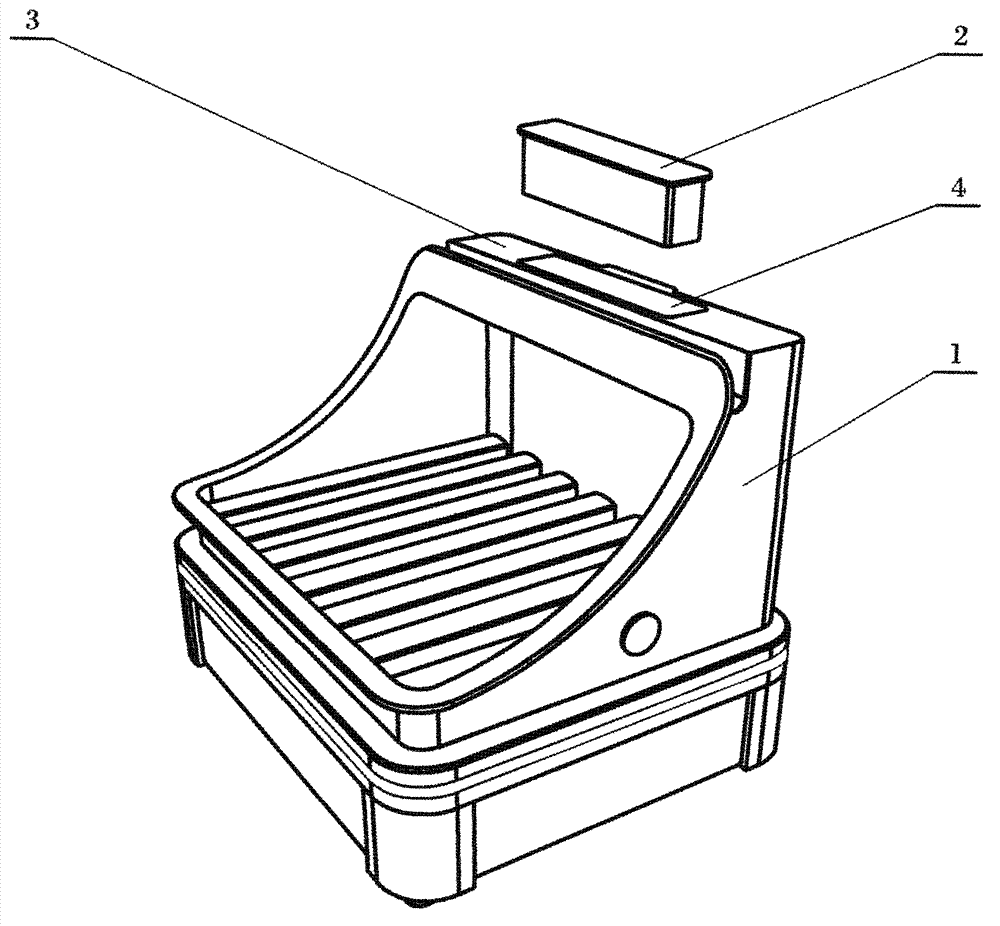
[0007] Embodiment of the present invention: a foot warmer with an electric control box on top is composed of a box body (1) and an electric control box (2), and an upper platform (3) is arranged on the upper part of the box body (1). (3) has an electric control box hole (4) in the middle, the size of the electric control box hole (4) matches the electric control box (2), and there are locking cards on both sides of the electric control box (2), which is convenient for electric control The box (2) is automatically locked after being embedded in the hole (4) of the electric control box.
Login to View More PUM
 Abstract
This invention relates to a foot warming box with an upper electric control box, belonging to the technical field of household electric heaters. The foot warming box with the upper electric control box consists of a box body and the electric control box and is characterized in that the upper part of the box body is provided with an upper platform; an electric control box hole is formed in the upper platform; and the electric control box is embedded in the electric control box hole. The foot warming box has the advantages that the electric control box of the foot warming box is upgraded to an upper device, the appearance grade of products is improved, and the comfort is obviously improved when the electric control box is operated for warming, so that the appearance and the applicability of the foot warming box have breakthrough improvement, and the foot warming box has an extremely good market prospect.
Description
Technical field [0001] The invention belongs to the technical field of household electric heaters, in particular to a foot warmer with an electric control box on top. Background technique [0002] The electric control boxes of the existing foot warmers are all placed on the side of the foot warmer, which is inconvenient to operate and unsatisfactory in use. Contents of the invention [0003] The object of the present invention is to provide a foot warmer with good use effect. [0004] In order to achieve the above object, the present invention is constituted as follows: a foot warmer with an electric control box on top is composed of a box body (1) and an electric control box (2), and an upper platform is arranged on the top of the box body (1) (3), the upper platform (3) has an electric control box hole (4), the size of the electric control box hole (4) coincides with the electric control box (2), so that the electric control box (2) can be inserted into the electric con...
Claims
Login to View More Application Information
Patent Timeline
 Patent Type & AuthorityApplications(China)
IPC IPC(8): A61F7/00
Inventor田双阁
Owner遵义航阳电器厂