Impact resistant device comprising an optical layer

An impact-resistant, optical layer technology, used in identification devices, photovoltaic modules, photovoltaic power generation, etc., can solve the problems of increasing the thickness and weight of the display, affecting the image quality of the display, blocking the visible range of the optical layer, etc., to achieve good impact resistance. Effect

Inactive Publication Date: 2013-01-30
SAMSUNG ELECTRONICS CO LTD
View PDF10 Cites 8 Cited by
  • Summary
  • Abstract
  • Description
  • Claims
  • Application Information

AI Technical Summary

Problems solved by technology

[0006] However, its disadvantage is that the method of providing a protective film may still block the visible range of the optical layer and affect the image quality of the display, and may also increase the unexpected thickness and weight of the display. There is still a great need for capacity

Method used


Image

  • Impact resistant device comprising an optical layer
  • Impact resistant device comprising an optical layer
  • Impact resistant device comprising an optical layer

Examples


Embodiment Construction

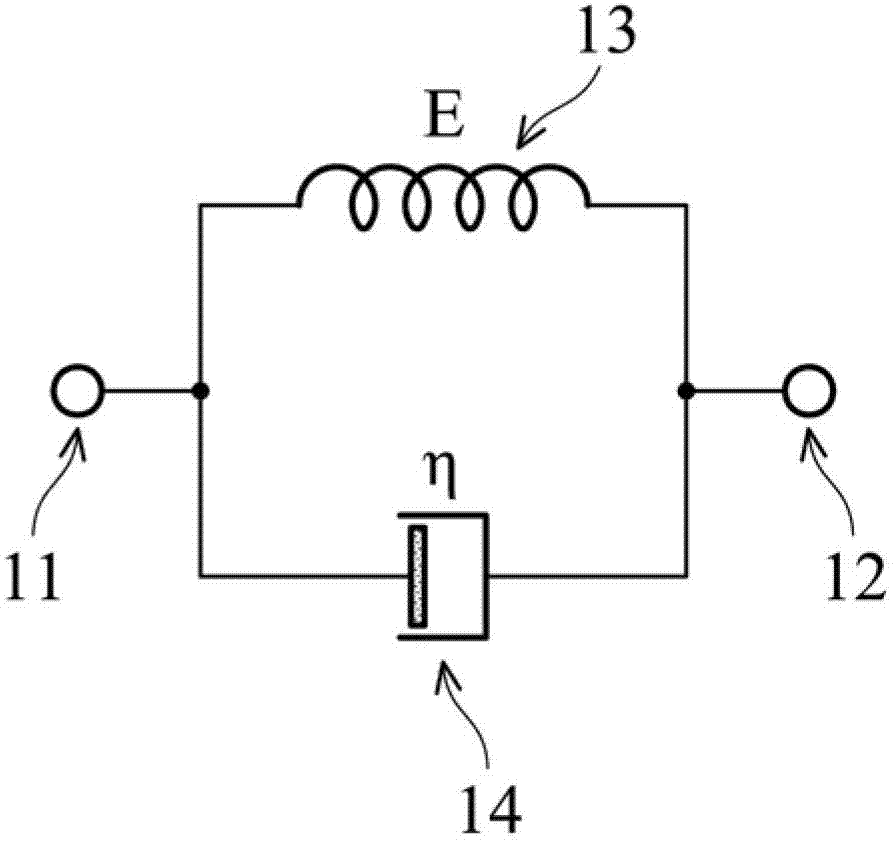
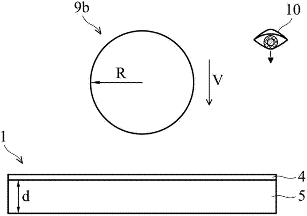
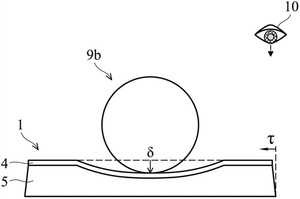
[0070] Please refer to the following paragraphs Figure 1-Figure 4 , one of the analysis methods is used to help evaluate the properties of the material to provide the exact impact resistance range required by the device. The following description is not limited to the specific model and derivation of the present invention. If other analysis, numerical or empirical methods Similar or even different information about the needs or ideals of the flexible sheet member and the back plate member can be provided, and both are included in the scope of the present invention.

[0071] An ultra-thin flexible sheet member includes an optical layer that, by virtue of its flexible nature, can allow relatively large deformations out of plane. For example, a display device has a flexible thin sheet member including an optical layer. When impacted by an object, the impact energy can be dissipated through a longer recess depth to reduce the burden on the internal structure of the device and pre...


PUM

PropertyMeasurementUnit
tackinessaaaaaaaaaa

Abstract

An impact resistant device includes an optical layer and electronics. The optical layer and electronics are comprised in a flexible foil structure which is supported by a backing structure in mechanical contact on a backside of the flexible foil structure. The backing structure includes a deformable material having a viscous response in a critical range, which critical range is defined for a given front impact event by a pressure threshold and a stretching threshold of the flexible foil structure such that the optical layer and electronics are not damaged by the impact event.

Description

technical field [0001] The present invention relates to an impact-resistant device having an optical layer, in particular an impact-resistant display device. Background technique [0002] The "shock resistance" mentioned below refers to the ability of a device or its single-layer structure to withstand shocks, for example, a device can maintain its normal function after being thrown or dropped. "Shock" is defined as the relative velocity of an impact between an object and a device exceeding 0.1m / s; "optical layer" is defined to include a single or composite layer that provides electromagnetic radiation, especially in Behaviors such as light absorption, emission, and penetration are carried out in the optical layer. The active function includes photoelectric energy conversion through light incident or absorbed by the optical layer; while the passive function includes selectively reflecting, penetrating or changing the light from the second light source. The optical layer is...

Claims


Application Information

Patent Timeline
Patent Type & Authority Applications(China)
IPC IPC(8): G09G3/34H01L31/048
CPCY02E10/52B32B27/40B32B27/065H01L31/1876H01L31/045G09F9/301Y02E10/50H01L31/0481G09F9/33H01L31/048H02S30/20Y02P70/50Y10T29/49826Y10T428/24942Y10T428/24998Y10T428/31551
Inventor L.M.博滕M.A.J.H.J.谢勒肯斯E.范维南达尔H.E.A.休伊特马
Owner SAMSUNG ELECTRONICS CO LTD
Why Eureka
Try Eureka