Mechanical shock test fixture for integrated circuit

An integrated circuit and mechanical shock technology, which is applied in the field of integrated circuit mechanical shock test fixtures, can solve the problem that the fixture cannot be used for high-acceleration shock tests, and achieve the effect of simple replacement of the direction

Inactive Publication Date: 2013-02-06
EAST CHINA INST OF OPTOELECTRONICS INTEGRATEDDEVICE
View PDF8 Cites 9 Cited by
  • Summary
  • Abstract
  • Description
  • Claims
  • Application Information

AI Technical Summary

Problems solved by technology

[0006] The purpose of the present invention is to solve the shortcoming that the jig for the impact test of integrated devices in the prior art cannot be applied to the high-acceleration impact test, and provides a jig for the mechanical impact test of integrated circuits

Method used


Image

  • Mechanical shock test fixture for integrated circuit
  • Mechanical shock test fixture for integrated circuit

Examples


Embodiment Construction

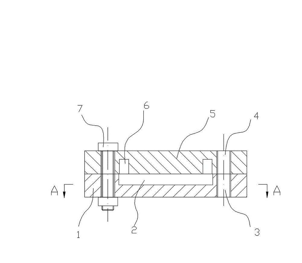
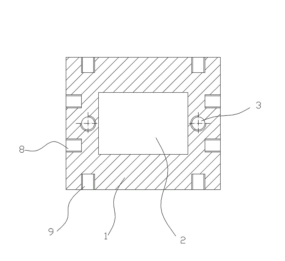
[0018] Such as figure 1 , figure 2 As shown, the integrated circuit mechanical impact test jig provided by the present invention comprises:

[0019] a. The base 1, the middle part of the base 1 is provided with a positioning groove 2 for holding the integrated circuit, the base 1 is provided with two bolt holes 3, and the side of the base 1 is respectively provided with an X-direction screw hole 8 and a Y-direction screw hole 9 ;

[0020] b. Cover plate 5, the middle part of the cover plate 5 is provided with a group of lead holes 6 matching with the positioning groove 2 in the base 1, and the cover plate 5 is provided with two bolt holes 4 matching with the base 1;

[0021] c. Cooperating bolts 7 are provided in the bolt holes on the base 1 and the cover plate 5 to connect the base 1 and the cover plate 5 together.

[0022] Working process of the present invention:

[0023] Such as figure 1 As shown, the integrated circuit is placed in the positioning groove 2 of the ba...


PUM


Abstract

The invention relates to a mechanical shock test fixture for an integrated circuit, which comprises that a base (1), a cover plate (5) and bolts, wherein a positioning groove (2) for containing the integrated circuit is formed in the middle of the base (1); at least two bolt holes (3) are formed in the base (1); a group of wire lead holes (6) matched with the positioning groove (2) in the base is formed in the middle of the cover plate (5); at least two bolt holes (4) matched with the base are formed in the cover plate (5); and the matched bolts (7) are arranged in the bolt holes in the base and the cover plate and connect the base and the cover plate into a whole. The fixture has the advantages that a circuit sample is completely nested into the fixture and completely matched with the fixture, so that the sample does not bear outside stress or slide under the conditions of progress and high acceleration (a peak value exceeding 100,000 g), and the completely actual shock resistance level of the sample is reflected. Shock tests in six directions can be achieved conveniently only by changing the connection direction of a mold, and the direction change is also very simple.

Description

technical field [0001] The invention relates to integrated circuit testing technology, in particular to an integrated circuit mechanical impact test jig. Background technique [0002] The acceleration test is one of the effective means to examine the internal structural strength of integrated circuits, the internal lead strength, the bonding strength of internal components, and the packaging strength. With the continuous expansion of the application range of integrated circuits, the acceleration test of integrated circuits is becoming more and more High (peak value over 100,000 g). [0003] At present, there are mainly two types of acceleration test fixtures: [0004] 1. Patent No.: 201020208344, patent name: Fixture for PCB board vibration and impact test; this patent mainly involves the fixing of PCB board for mechanical impact test. Screw holes and support columns are used to fix the sample. During the mechanical impact test of the microcircuit, since the additional for...

Claims


Application Information

Patent Timeline
Patent Type & Authority Applications(China)
IPC IPC(8): B25B11/00G01M7/08
Inventor 肖勇兵明灵
Owner EAST CHINA INST OF OPTOELECTRONICS INTEGRATEDDEVICE
Why Eureka
Try Eureka