Supercharge Your Innovation With Domain-Expert AI Agents!

Light-emitting diode

A technology of light-emitting diodes and light-emitting chips, which is applied in the direction of electrical components, electric solid-state devices, circuits, etc.

Inactive Publication Date: 2015-02-04
ZHANJING TECH SHENZHEN +1
View PDF3 Cites 0 Cited by
  • Summary
  • Abstract
  • Description
  • Claims
  • Application Information

AI Technical Summary

Problems solved by technology

However, in some applications, it is required that the light-emitting diodes have a relatively strong luminous intensity on the side, and the existing light-emitting diodes cannot meet the requirements of this application

Method used


Image

  • Light-emitting diode
  • Light-emitting diode
  • Light-emitting diode

Examples


Embodiment Construction

[0014] The present invention will be further described in detail below in conjunction with the accompanying drawings.

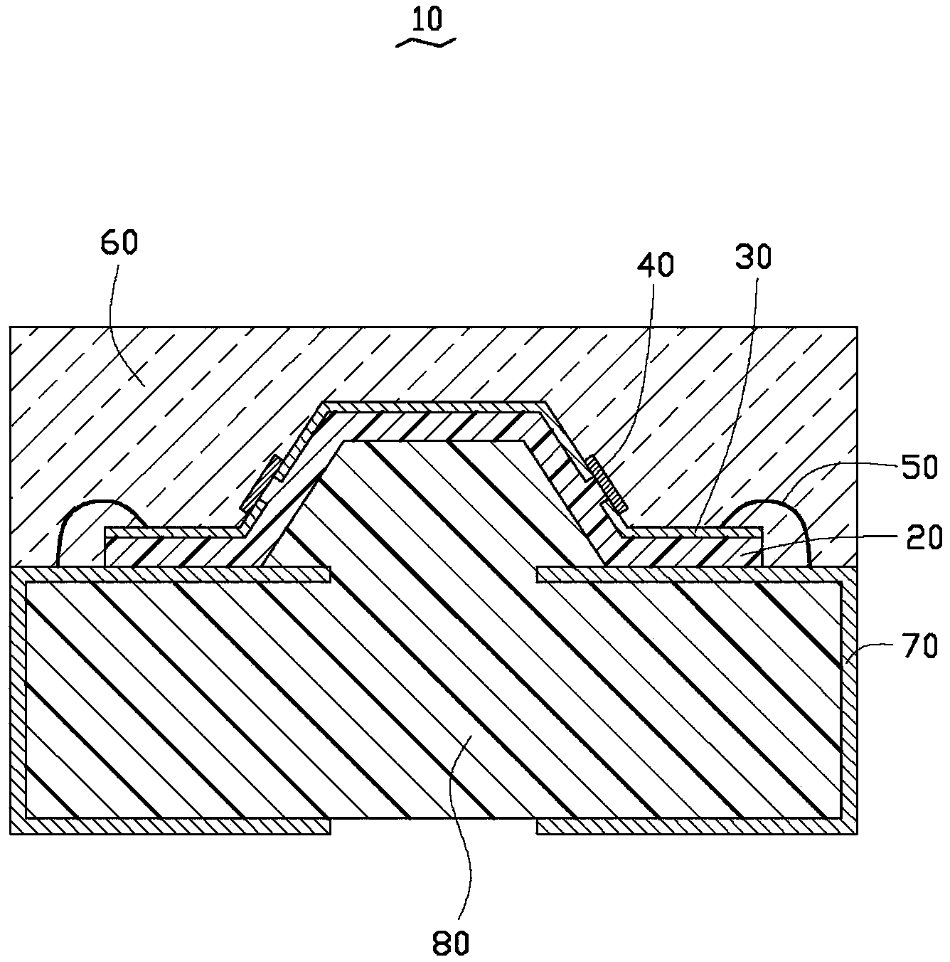
[0015] see Figure 1-3 , shows the light emitting diode 10 of the first embodiment of the present invention and two steps of its manufacturing process. The LED 10 includes a substrate 20 , a conductive plate set 30 , two light-emitting chips 40 , a package 60 , a base 80 , two conductive modules 70 , and wires 50 connecting the conductive plate set 30 and the conductive modules 70 .

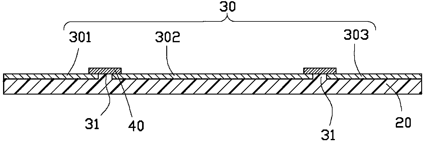
[0016] The substrate 20 is a flexible substrate 20 which can be bent into a shape through processing. The conductive plate group 30 covers the substrate 20 and has openings 31 at distances from the left and right borders of the substrate 20 about a quarter of the total length of the substrate 20 . The opening 31 divides the conductive plate set 30 into a first conductive plate 301 , a second conductive plate 302 and a third conductive plate 303 from left to right. The conduct...
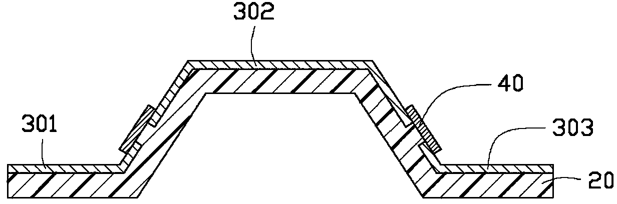

PUM


Abstract

The invention discloses a light-emitting diode, which comprises a conductive plate, lighting chips, a packaging body and a substrate, wherein the conductive plate comprises a first conductive plate and a second conductive plate, which are insulated with each other; the lighting chips are electrically connected to the first conductive plate and the second conductive plate; the lighting chips are inclined relative to the substrate to enable the emergent surface of the lighting chips to be toward one side of the light-emitting diode; and light generated by the emergent surface of the lighting chips is ejected out from the side of the light-emitting diode through the packaging body. As the lighting chips are distributed on the two sides of the light-emitting diode, side-direction lighting of the light-emitting diode is enhanced.

Description

technical field [0001] The invention relates to a light emitting diode, in particular to a light emitting diode with enhanced side light emission. Background technique [0002] The light-emitting diode industry is one of the most eye-catching industries in recent years. Up to now, light-emitting diode products have the advantages of energy saving, power saving, high efficiency, fast response time, long life cycle, mercury-free, and environmental protection benefits. , so it is considered to be the best light source for the new generation of green energy-saving lighting. In the existing packaging methods of light-emitting diodes, when emitting light, the middle luminous intensity is stronger, and the side luminous intensity is weaker. However, in some applications, it is required that the light-emitting diodes have relatively strong luminous intensity on the side, and the existing light-emitting diodes cannot meet the requirements of this application. Contents of the inven...

Claims


Application Information

Patent Timeline
Patent Type & Authority Patents(China)
IPC IPC(8): H01L33/48H01L25/075
Inventor 罗杏芬
Owner ZHANJING TECH SHENZHEN
Features
  • R&D
  • Intellectual Property
  • Life Sciences
  • Materials
  • Tech Scout
  • Unparalleled Data Quality
  • Higher Quality Content
  • 60% Fewer Hallucinations
Learn More