Method for controlling a compressor

A compressor, inlet pressure technology, applied in pump control, mechanical equipment, machine/engine, etc., can solve problems such as high manufacturing cost, low dependence on centrifugal compressors, high complexity, etc.

Active Publication Date: 2013-02-06
ATLAS COPCO AIRPOWER NV
View PDF5 Cites 6 Cited by
  • Summary
  • Abstract
  • Description
  • Claims
  • Application Information

AI Technical Summary

Problems solved by technology

The disadvantages of this approach are: the relatively high complexity and relatively high manufacturing costs that come with it
[0016] However, the disadvantage of this approach is that, since the power of the centrifugal compressor is not very dependent on the final pressure, huge losses occur during the transition between the load state and the no-load state or vice versa

Method used


Image

  • Method for controlling a compressor
  • Method for controlling a compressor

Examples


Embodiment Construction

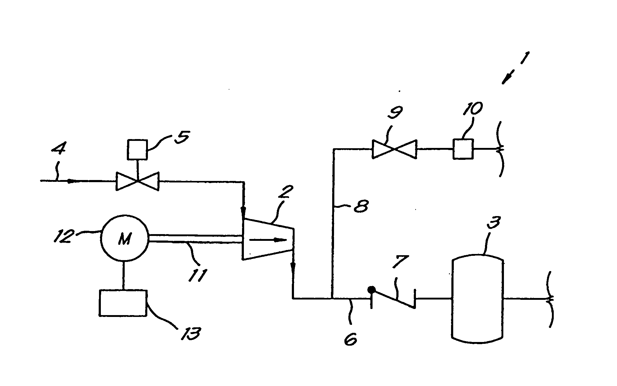
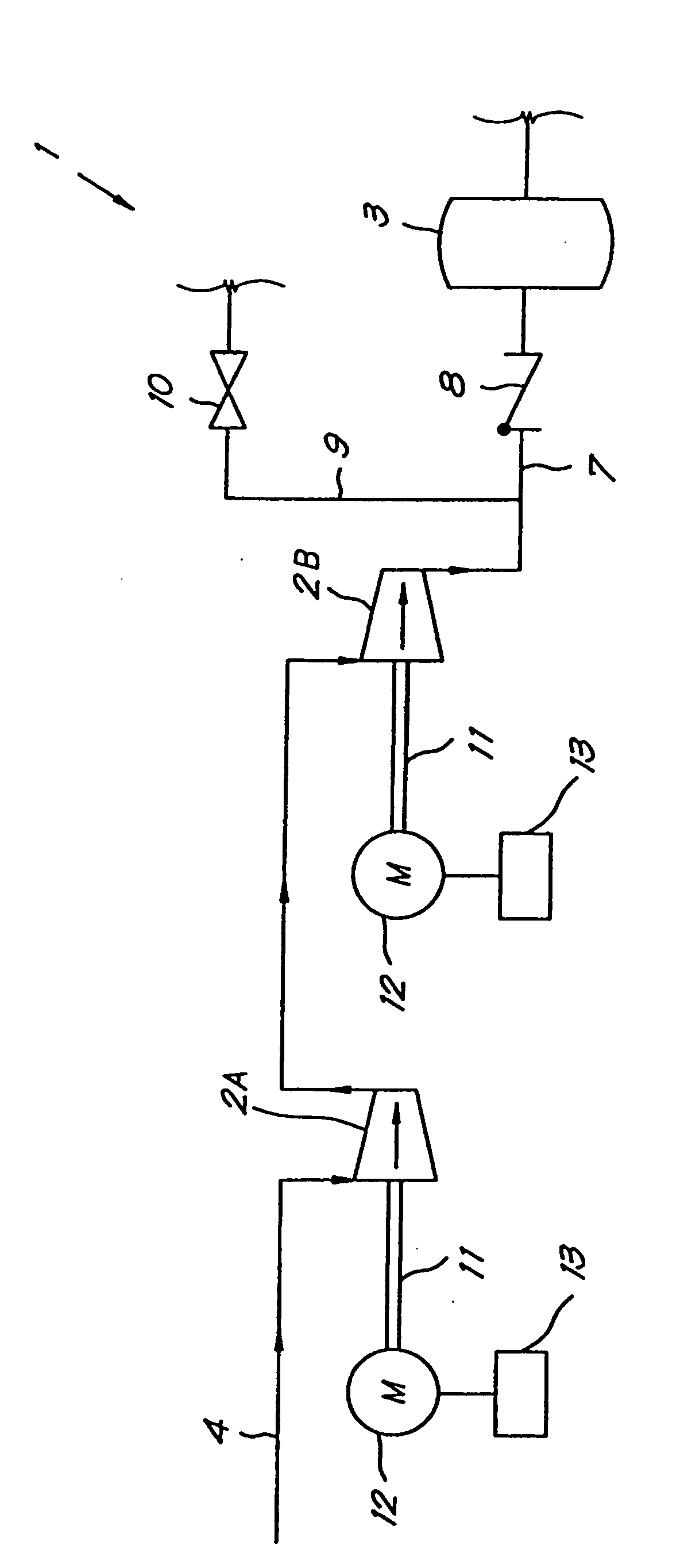
[0035] figure 1 A compressor 1 is shown, comprising, in this non-limiting example, only one compressor unit 2 (in the present solution said compressor unit is of the turbo type), which contributes to Compressed gas is supplied by a pressure network 3 which is connected to one or more compressed gas consumers.

[0036] An inlet pipe on the inlet side of the compressor unit 2 is provided with an inlet valve 5 , said inlet pipe being connected to the gas to be compressed inlet of the compressor unit 2 .

[0037] In this solution, the inlet valve 5 is configured such that it allows a certain minimum flow of gas to flow through the compressor unit 2 even in the fully closed state, but this configuration is not necessary. According to a modification not shown in the drawings, such an inlet valve 5 can be realized, for example (but not necessarily) by configuring the inlet valve 5 as a shut-off valve with a bypass pipe passing through it, and when the shut-off valve is fully closed ...


PUM


Abstract

Method for controlling a compressor that contains a compressor element, characterised in that during a transition from full load or partial load to zero load, a process A is followed that comprises the following steps:- the reduction of the inlet pressure; - the reduction of the speed and / or the drive torque, and / or during a transition from zero load to partial load or full load, a process B is followed that comprises the following steps: - increase of the speed or drive; and - the increase of the inlet pressure.

Description

technical field [0001] The invention relates to a method of controlling a compressor having one or more compressor units, each compressor unit being equipped with an inlet and an outlet, thereby enabling the compressor to be connected to a load using compressed gas . [0002] More specifically, the object of the invention is to save energy during the transition from full load or part load to zero load or vice versa, whereby the compressor comprises a control unit that integrates one of the above-mentioned compressor units or The speed of a plurality of the above-mentioned compressor units is controlled at a rated speed or within a certain rated speed range. Background technique [0003] In many cases, for example where a compressor supplies compressed gas to a pressure network, it is desirable that the flow of compressed gas at the outlet of the compressor can be controlled to a certain extent. In this case, the supplied gas flow is preferably regulated according to the co...

Claims


Application Information

Patent Timeline
Patent Type & Authority Applications(China)
IPC IPC(8): F04D17/12F04D27/02
CPCF04D27/0261F04D27/0284F04D17/12Y02B30/70F04D27/0215F05D2210/12Y10S415/00Y10S417/00
Inventor F·G·M·休伯兰德S·J·R·J·扬森斯U·帕纳F·P·I·拜恩斯
Owner ATLAS COPCO AIRPOWER NV
Why Eureka
Try Eureka