Riveting production equipment

A production equipment and riveting technology, applied in the field of manufacturing, can solve the problems of explosion, concentration, and damage to surrounding circuits, and achieve the effect of improving the strength of lightning resistance and solving the problem of failure.

Inactive Publication Date: 2013-02-13
张荣群
View PDF0 Cites 2 Cited by
  • Summary
  • Abstract
  • Description
  • Claims
  • Application Information

AI Technical Summary

Problems solved by technology

As a physical method, during the riveting process, physical damage will inevitably be caused around the working point. The most common is the formation of some fine sharp burrs around the riveting point of the guide foil; after a large number of failed high-voltage capacitors Through anatomical analysis, it is found that it is precisely because of the existence of these sharp burrs around the pressure point of the guide foil riveting (especially the negative electrode), that a large amount of charge is concentrated around this part. When the charge accumulates to a certain extent and exceeds the flash point of the electrolyte, it will It will cause high-voltage discharge, and the arc will break down the electrolyte and the positive and negative electrode foils to cause a short circuit. In extreme cases, it will even explode, which will damage the surrounding circuits.

Method used


Image

  • Riveting production equipment

Examples


Embodiment Construction

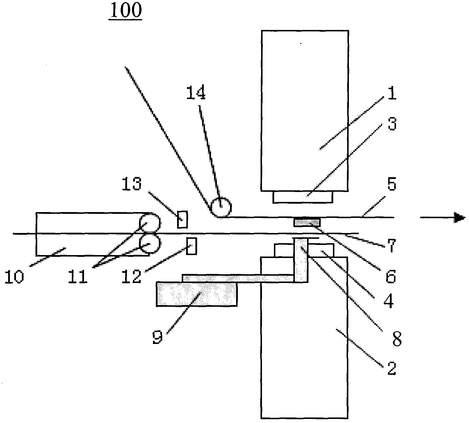
[0013] Please refer to the figure, it is a kind of riveting production equipment 100 provided by the present invention, which includes riveting upper film assembly 1, riveting lower die assembly 2, riveting upper die 3, riveting lower die 4, negative electrode aluminum foil 5, guide foil 6 , pad foil 7, foil guide bracket 8, cylinder assembly 9, feeding assembly 10 provided with feeding master-slave roller 11, pad foil scissors 12, 13 and guide wheel 14 for guiding the negative aluminum foil 5.

[0014] The riveting upper die assembly 1 and the riveting lower die assembly 2 are vertically oppositely arranged, and the riveting upper die 3 and the riveting lower die 4 are arranged opposite to each other with a movable A channel through which the negative electrode aluminum foil passes, and the guide foil 6 is arranged in the channel and under the negative electrode aluminum foil. The riveting lower die assembly 2 is connected with the cylinder assembly 9 , and the foil guide bra...


PUM


Abstract

The invention provides riveting production equipment, which comprises a riveting upper mold assembly, a riveting lower mold assembly, a riveting upper mold and a riveting lower mold; a cathode aluminum foil, a guide foil and a cushion foil are arranged between the riveting upper mold and the riveting lower mold; the riveting lower mold assembly is provided with a guide foil bracket and a steam cylinder assembly for controlling the guide foil bracket; the guide foil bracket is positioned below the cushion foil; the guide foil and the cushion foil are positioned below the cathode aluminum foil; and the guide coil is positioned between the cathode aluminum foil and the cushion foil. Compared with the prior art, the riveting production equipment has the advantages that a damaged part of the guide foil is concealed, the lightning stroke resisting strength of the cathode aluminum foil is improved, damage on a main electrode foil due to discharge of high-voltage electric charges is effectively avoided, and the problem that a high-voltage aluminum electrolytic capacitor fails is solved.

Description

【Technical field】 [0001] The patent of the present invention relates to the field of manufacturing, especially the riveting production equipment used in the riveting production process. 【Background technique】 [0002] The guide foil or guide pin (or "lead") is riveted onto the positive and negative polarized aluminum foil by riveting (cold riveting or rivet riveting); the quality of the riveting directly determines the final performance of the aluminum electrolytic capacitor. quality and longevity. As a physical method, during the riveting process, physical damage will inevitably be caused around the working point. The most common is the formation of some fine sharp burrs around the riveting point of the guide foil; after a large number of failed high-voltage capacitors Through anatomical analysis, it is found that it is precisely because of the existence of these sharp burrs around the pressure point of the guide foil riveting (especially the negative electrode), that a la...

Claims


Application Information

Patent Timeline
Patent Type & Authority Applications(China)
IPC IPC(8): H01G13/00
Inventor 张荣群
Owner 张荣群
Why Eureka
Try Eureka